Page 25
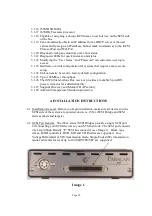
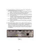
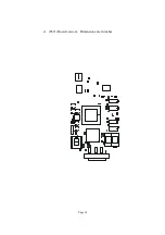
4.10 LEDs. There are 5 LEDs on the iSCSI Bridge that can be used for
status/diagnostics (see Image 2 of section 4.6)
4.10.1
SCSI Activity (Yellow). The SCSI Activity LED is labeled “SCSI” on
the iS520 and iS550. During normal operation, this LED turns on
when there is SCSI activity on the SCSI bus. However, the LED will
also indicate when there are no SCSI targets on the SCSI bus. After
initial boot, i.e. after the Status LED has turned solid green, if the
SCSI Activity LED is continuously blinking at a constant half second
rate, the unit has found no targets on the SCSI bus.
4.10.2
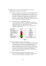
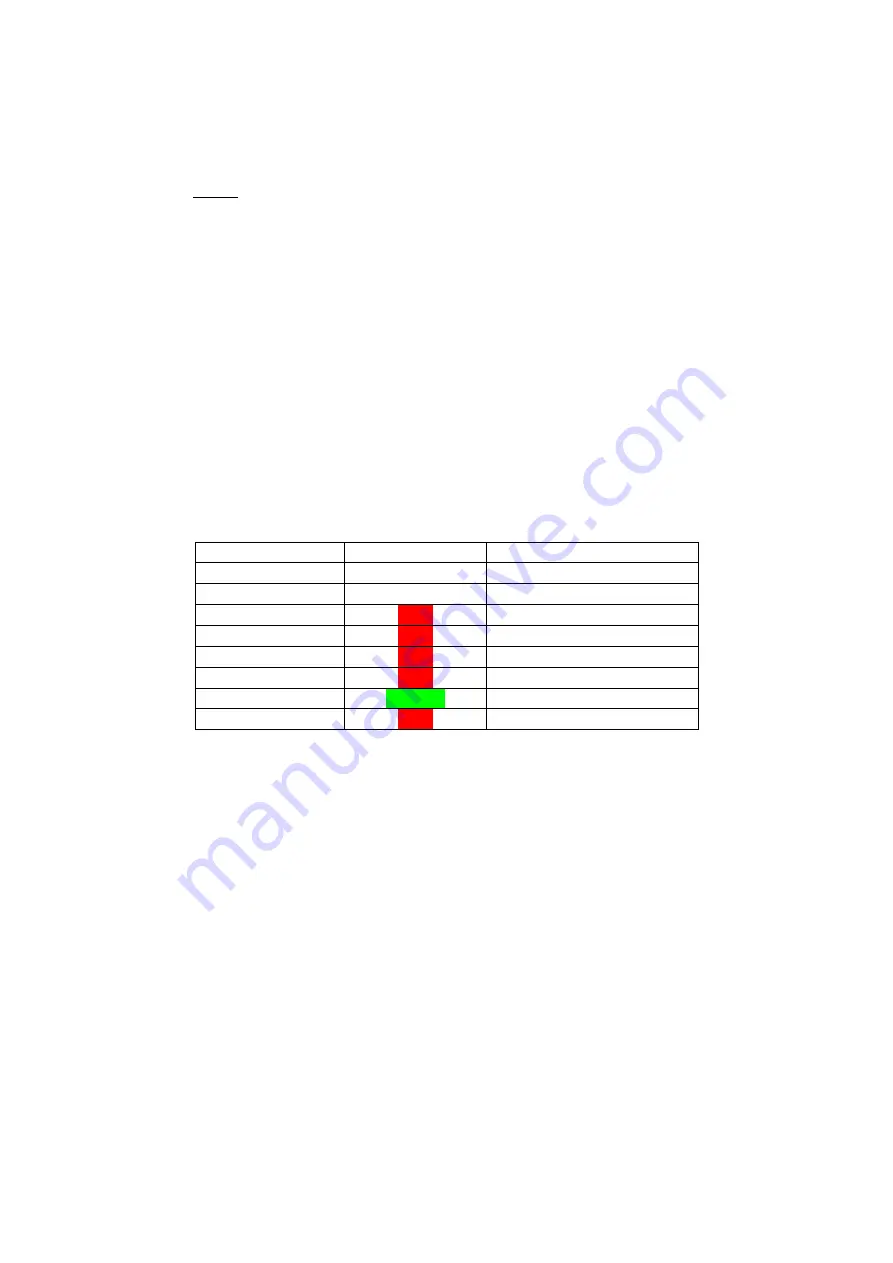
Status (Red/Green). The Status LED is labeled
“STAT” on the iS520 and iS550. The Status LED identifies what
stage the boot process is in. It also notifies the user when an update is
being loaded into the unit by turning solid red. Once
the update is complete, the LED will return to a solid green state.
Please refer to table 3 below.
Description
Color
State
Boot Loader
OFF
OFF
Operating System
N/A
SOLID
Network Interface
RED
5 BLINKS
Web-based Utility
RED
3 BLINKS
SCSI
RED
2 BLINKS
iSCSI
RED
4 BLINKS
Boot Complete
GREEN
SOLID
Updating Unit
RED
SOLID (During Burning)
Table 3
4.10.3
Power (Red/Green). The Power LED is labeled
“PWR” on the iS520 and iS550. This LED will turn solid green when
there is sufficient power to the unit. The LED will turn off when the
unit is NOT powered. The LED will turn solid RED when the
immediate ambient temperature has exceeded 65
°
C. The unit will be
held in reset and the user will not be able to communicate with it once
in this state. If the user wishes to restart the unit first bring the
ambient temperature down to an acceptable level (<40
°
C), wait 10
minutes and press the reset button.
4.10.4
Ethernet Data (Green). The Ethernet Data LED is labeled
“DATA” on the iS520 and iS550. This LED turns on when there is
activity to/from the iSCSI Bridge on the Ethernet network.


