Copyright © Parallax Inc.
Mouse Sensor Kit (#28560)
v1.0 6/1/2010 Page 5 of 18
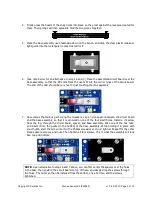
4. Firmly press the heads of the snap rivets into place so they rest against the recesses created for
them. Their prongs will then spread to hold the two pieces together:
5. Place the base assembly rivet-head-side-down on the bench, and drop the clear plastic lens-and-
light guide into the rectangular recess created for it:
6. (See note below for an alternative to steps 6 and 7.) Place the assembled circuit board over the
base assembly, so that the little nibs from the rivets fit into the corner holes of the circuit board.
The end of the LED should be very near or just touching the lens assembly:
7. Now comes the tedious part. Using the tweezers, slip a nylon spacer between the circuit board
and the base assembly, so that it is centered on one of the four small holes. Install a #2 screw
from the top, through the circuit board, spacer, and base assembly. Take one of the hex nuts,
and insert it into the pocket in the bottom of the base assembly. While holding it in place with
your thumb, start the screw into it with a Phillips screwdriver.
Do no tighten.
Repeat for the other
three spacers, screws, and nuts. Then tighten all four screws. This is what the assembly will look
like, top and bottom:
NOTE:
As an alternative to steps 6 and 7 above, you can first center the spacers over the holes
in the base, then position the circuit board on top of these, and simply drop the screws through
the holes. The nuts can then be installed from the bottom, one at a time, and the screws
tightened.


