Copyright © Parallax Inc.
Eddie Robot Platform (28990 & 28992)
v1.1 1/16/2013 Page 11 of 17
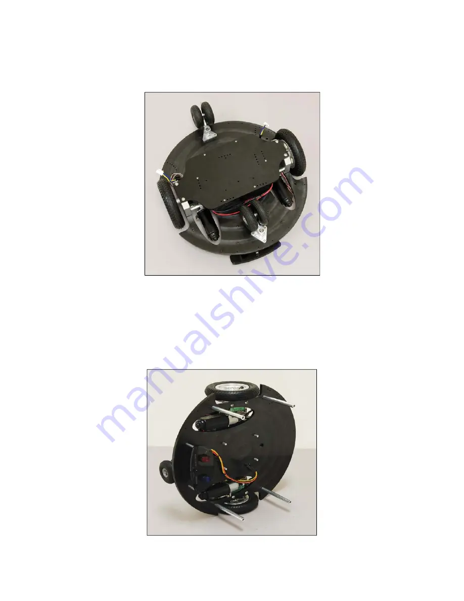
Place the pre-assembled Battery Shelf over the cells and slide it into alignment so that the the thru holes
line up with the tapped holes in the Motor Bearing Block. Secure the Battery Tray with (4) ¼-20 x ½”
long button head screws, as shown in Figure 7c.
Figure 7c
Step 8: Switch Plate and 5” Upper Deck Supports Installation
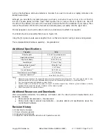
Place the assembly on its side, as shown in Figure 8a. Attach (4) ½” diameter by 5” long machined
aluminum standoffs with ¼-20 x 5/8” long button head screws as shown.
Connect the Switch Plate to the (4) 1.5” tall standoffs with (4) #4-40 x ½” long black, Phillips head
screws, as shown in Figure 8a as well.
Figure 8a


