Copyright © Parallax Inc.
Eddie Robot Platform (28990 & 28992)
v1.1 1/16/2013 Page 13 of 17
Viewing Eddie from the front, (as in Figure 9a), connect the left-most IR Sensor cable to “AD1”, the
center IR sensor to “AD2”, and the right-most IR Sensor to “AD3”. Connect the left-most Ping))) to I/0
“1” and the right-most Ping))) to I/O “2” on the Eddie Control Board. Be sure to observe proper polarity
– the black wires (ground) should be attached to the outer-most pins of the 3-pin headers.
Connect the left-most (towards the outer edge of the deck) three-pin cable from the left Encoder to
header pin 9 on the I/O section of the Control Board. The black wire should be on the outer-most pin of
the three-pin header. Now connect the other Encoder cable to header pin 10 on the Control board.
Connect the right-side motor’s innermost cable into header pin 11 on the Control Board, and then the
final Encoder cable to header pin 12. Be certain that all the black wires are oriented towards the outside
edge of the Board.
Locate the power enable switch on the Control Board near the USB connector. Slide the “Motors – Board
– Off” switch to the “Motors” position (all the way closest to the USB connector). This switch will leave
board power and motor power enabled since they are switched externally using the high-current red and
blue power switches.
Step 10: Second Deck Installation
The Second Deck’s “top” side is indicated by the (4) counter-sunk holes that line up with the (4) 5” long
aluminum standoffs. The “counter sink” is the top.
Attach the two 12” long standoffs to the Second Deck by inserting (2) ¼ - 20 x 5/8” button head screws
from the bottom side of the Second Deck.
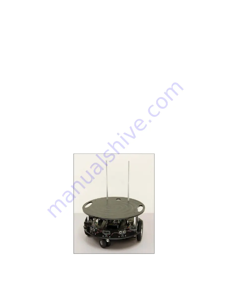
Place the Second Deck onto the 5” standoffs as shown in Figure 10, and fasten with (4) ¼ -20 Flat head
Black Screws.
Figure 10


