Page 194 ·
Robotics with the Boe-Bot
A photoresistor
is a light-dependent resistor (LDR) that covers the spectral sensitivity
similar to that of the human eye. In other words, the kind of light that your eye detects is the
same kind of light that affects the photoresistor’s resistance. The active elements of these
photoresistors are made of Cadmium Sulfide (CdS). Light enters into the semiconductor
layer applied to a ceramic substrate and produces free charge carriers. A defined electrical
resistance is produced that is inversely proportional to the illumination intensity. In other
words, darkness causes more resistance, and brightness causes less resistance.
Illuminance
is a scientific name for the measurement of incident light. One way to
understand incident light is to think about shining a flashlight at a wall. The focused beam
that you see shining on the wall is incident light. The unit of measurement of illuminance is
commonly the "foot-candle" in the English system or the "lux" in the metric system. While
using the photoresistors we won't be concerned about lux levels, just whether illuminance is
higher or lower in certain directions. The Boe-Bot can be programmed to use the relative
light intensity information to make navigation decisions.
ACTIVITY #1: BUILDING AND TESTING PHOTORESISTOR CIRCUITS
In this activity, you will build and test light level sensor circuits with photoresistors.
Your light level sensor circuits will be able to detect the difference between shade and no
shade. The PBASIC commands for determining whether a shadow is cast over the
photoresistor will be very similar to those used to determine whether or not a whisker has
contacted an object.
Parts List:
(2) Photoresistors - CdS
(2) Resistors – 2 k
Ω
(red-black-red)
(2) Resistors – 220
Ω
(red-red-brown)
(4) Jumper wires
(2) Resistors – 470
Ω
(yellow-violet-brown)
(2) Resistors – 1 k
Ω
(brown-black-red)
(2) Resistors – 4.7 k
Ω
(yellow-violet-red)
(2) Resistors – 10 k
Ω
(brown-black-orange)
Building the Photosensitive Eyes
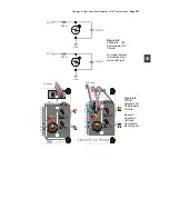
Figure 6-2 shows the schematic and Figure 6-3 shows the wiring diagram for the
photoresistor circuits you will use in this and the next two activities.
√
Disconnect power from your board and servos.
√
Build the circuit shown in Figure 6-2, using Figure 6-3 as a reference.


