Chapter 3: SumoBot Sensors and Border Detection · Page 23
Chapter 3: SumoBot Sensors and Border Detection
Once the SumoBot is moving, the next task is to scan the playing surface to make sure
that it doesn't drive itself out of the ring. The task is accomplished by two specialized
line detection sensors called QTIs. The QTI uses a reflective infrared sensor to allow the
SumoBot to "look" for the ring's border.
LINE SENSOR THEORY
The Parallax QTI uses a QRD1114 infrared (IR) reflective sensor to determine the
reflectivity of the surface below it. When the SumoBot is over the black playing field or
start lines (Shikiri), the reflectivity is very low; when the QTI is over the white border
(Tawara), the reflectivity is very high and will cause a different reading from the sensor.
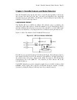
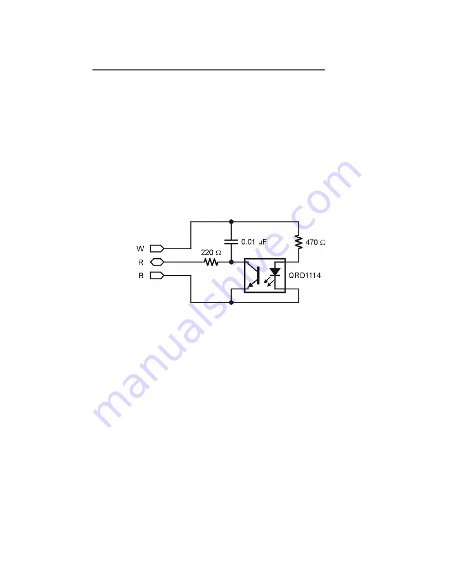
Figure 3.1 shows the schematic for the Parallax QTI line sensor.
Figure 3.1: QTI Line Sensor Schematic
The QTI sensor is activated by placing 5V (Vdd) on the W pin. This will cause current to
flow through the 470
Ω
resistor to the LED side of the QRD1114. IR light reflecting of
the surface below will cause a change in the ability for current to flow through the
phototransistor side of the QRD1114. The transistor, in effect, behaves like an IR
controlled resistance.
The BASIC Stamp has a specific command designed to read a variable resistance called
RCTIME
. When coupled with a capacitor, the BASIC Stamp can measure a variable
resistance by timing the charge or discharge rate of the connected capacitor.
Summary of Contents for Boe-Bot
Page 1: ...SumoBot Mini Sumo Robotics Assembly Documentation and Programming VERSION 2 1...
Page 4: ......
Page 9: ...Preface Page ix...
Page 10: ......
Page 20: ......
Page 32: ......
Page 54: ......
Page 74: ......
Page 76: ......
Page 77: ...Appendix D SumoBot PCB Schematic Page 67 Appendix D SumoBot PCB Schematic...


