Attach the Mount to the ELEV-8 V2 Frame
Setup Instructions
1. Use the Hacksaw to cut the Aluminum Channel to length per the technical drawing
included with this download: Aluminum Channel Technical Drawing.
2. Use the Metal File to round all sharp edges and chamfer the ends of the Aluminum
Channel.
3. Measure out and mark the locations of the four holes in the Aluminum Channel.
4. Drill out the four holes in the Aluminum Channel, then remove and burrs.
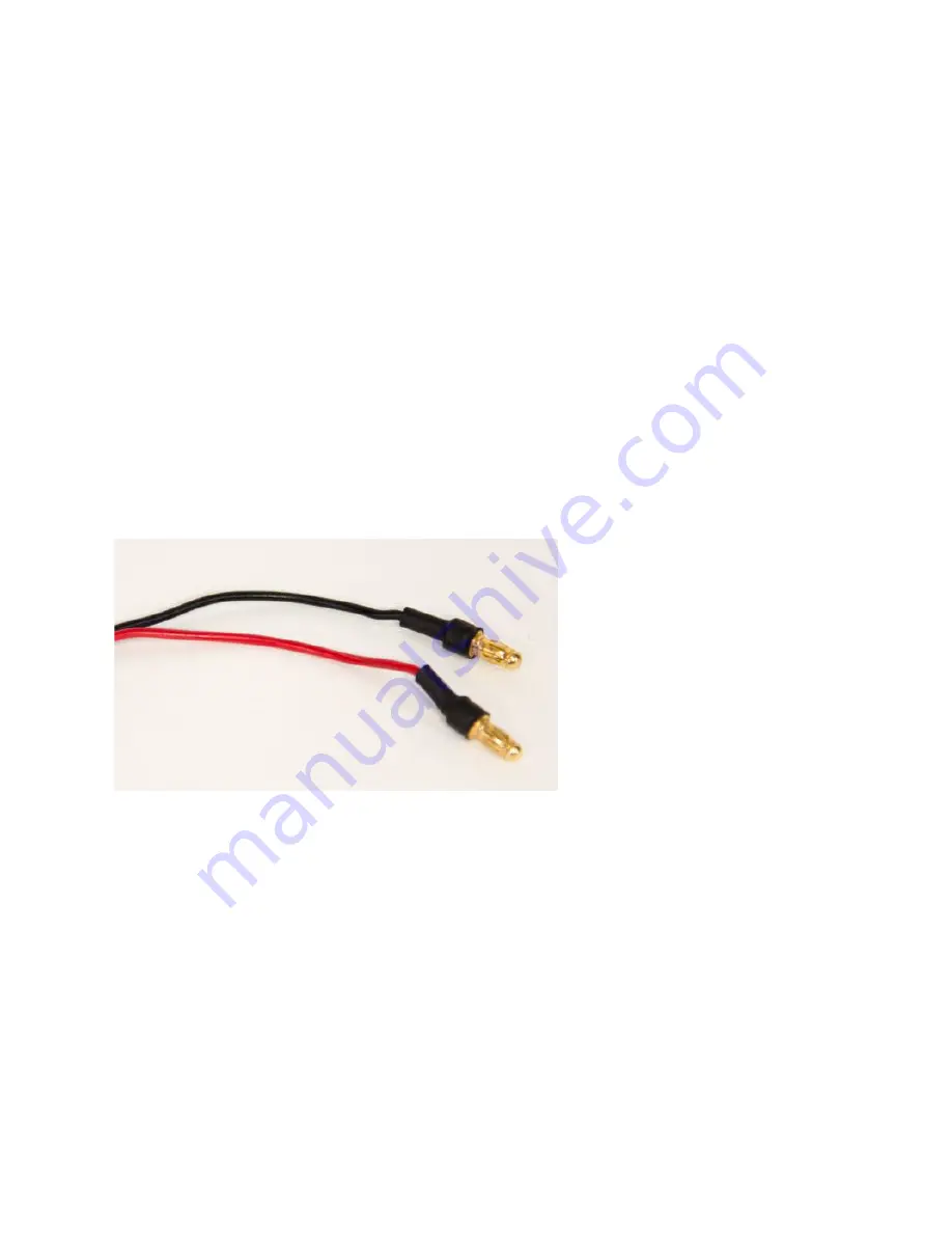
5. Solder Male Bullet Connectors onto the ends of the red/black power cable connected to
the Gimbal Control Board. See the ELEV-8 V2 Assembly Guide for Soldering
Instructions.
6. Apply Heat-shrink tubing to the two bullet connectors, as detailed in the ELEV-8 V2
Assembly Guide and shown in the image below.
7. Remove the bottom plate from the ELEV-8 to access the power distribution cable
outputs. Plug the Bullet Connectors you just soldered into the available auxiliary outputs
and route the cables towards the front of the ELEV-8. Replace the bottom plate.
8. Plug the Signal Cable Splitter that came with the Gimbal into the CTR port on the Gimbal
Control Board, in the orientation shown below. Slowly and gently bend the plug towards
the center of the board, as shown below.
Copyright © Parallax Inc.
Add a Gimbal Mount to Your ELEV-8 V2
07/30/2018 Page 4 of 8


