Copyright © Parallax Inc.
Penguin Robot (#27313-27316)
v1.4 2/16/2010 Page 6 of 23
Step 2: Center the servos using the BASIC Stamp Editor
This step centers the servos, so that further mechanical tuning will be minimized once the Penguin is
assembled. It also ensures that you won’t need to take the Penguin apart once you start programming it.
The servos need to be centered with a 1.5 ms pulse, following the directions below:
a.
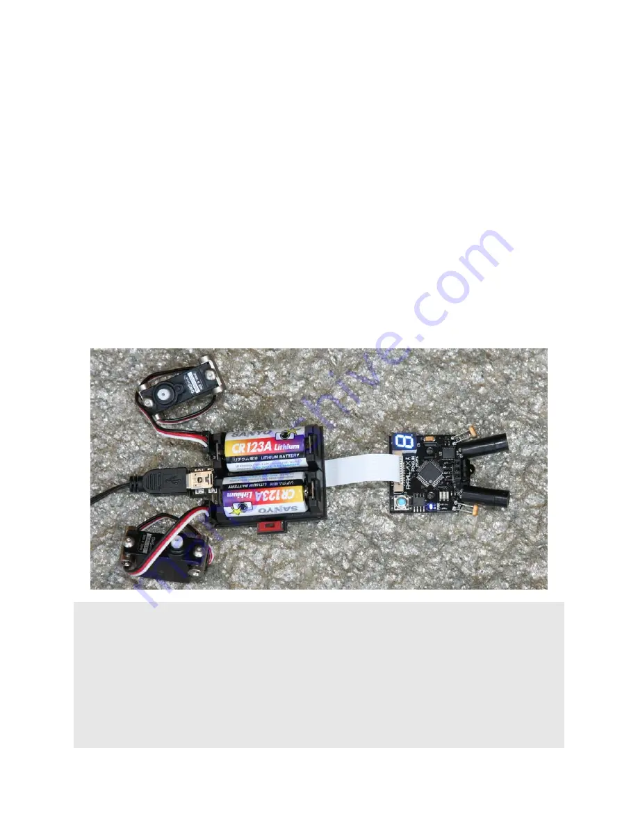
Connect the Penguin boards together using the flat ribbon cable, as pictured. For boards with a
"REV B" label near the 7-segment display, the blue-tipped side of the cable faces toward the
Parallax logo. Otherwise, the blue-tipped side of the cable faces away from the Parallax logo.
b.
Insert two (2) CR123 batteries into the power pack. A line drawing on the inside of the battery
holder shows how the batteries are oriented. (Orientation may differ from picture shown.)
c.
Plug two servos into the bottom of the power pack, being careful to orient them correctly. From
the perspective of this photo, the servo’s white leads are on the bottom, or the right side of each
servo connector as viewed behind the Penguin.
d.
Download and install the BASIC Stamp Editor and FTDI USB VCP drivers software if you have not
done so already.
e.
Plug the mini USB cable into the power pack.
f.
Plug the other end of the USB cable into your PC.
g.
Turn on power to the board (slide the switch toward the ribbon cable).
h.
Open the BASIC Stamp Windows Editor and run the Penguin-CenterServos.bpx program.
i.
The servos are now centered. Disconnect the servos first, and then remove the batteries and USB
cable from the power pack board.
' Parallax Penguin Robot
' Penguin-CenterServos.bpx
' {$STAMP BS2px}
' {$PBASIC 2.5}
Center CON 1875 ' Centered servo pulse
StrideServo PIN 6
TiltServo PIN 7
DO
PULSOUT StrideServo, Center ' Center stride servo (J1)
PULSOUT TiltServo, Center ' Center tilt servo (J2)
PAUSE 15
LOOP
Summary of Contents for Penguin
Page 24: ......


