Copyright © Parallax Inc.
PING))) Ultrasonic Distance Sensor (#28015)
v2.0 2/4/2013 Page 6 of 9
Example Programs
BASIC Stamp 2
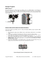
This circuit allows you to quickly connect your PING))) sensor to a BASIC Stamp
®
2 via the Board of
Education
®
breadboard area. The PING))) module’s GND pin connects to Vss, the 5 V pin connects to
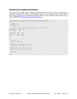
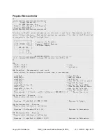
Vdd, and the SIG pin connects to I/O pin P15. This circuit will work with the example BASIC Stamp
program listed below.
Extension Cable and Port Cautions for the Board of Education
If you are connecting your PING))) sensor to a Board of Education platform using an extension cable,
follow these steps:
1.
When plugging the cable onto the PING))) sensor, connect Black to GND, Red to 5 V, and White
to SIG.
2.
Check to see if your Board of Education servo ports have a jumper, as shown at right.
3.
If your Board of Education servo ports have a jumper, set it to Vdd as shown. Then plug the
cable into the port, matching the wire color to the labels next to the port.
4.
If your Board of Education servo ports do not have a jumper,
do not use them with the
PING))) sensor
. These ports only provide Vin, not Vdd, and this may damage your PING)))
sensor. Go to the next step.
5.
Connect the cable directly to the breadboard with a 3-pin header as shown above. Then, use
jumper wires to connect Black to Vss, Red to Vdd, and White to I/O pin P15.
Board of Education Servo Port Jumper, Set to Vdd


