background image

FL-33

LAT-ROW

ASSEMBLY MANUAL

Rev 03/04

AM-FL-33

F

ITNESS

 L

INE

 C

IRCUIT

®

INNOVATIVE


STRENGTH


SYSTEMS

Summary of Contents for FL-33

Page 1: ...FL 33 LAT ROW ASSEMBLY MANUAL Rev 03 04 AM FL 33 FITNESS LINE CIRCUIT INNOVATIVE STRENGTH SYSTEMS...

Page 2: ...e selector bar is no greater than 1 3 8 inches see installation Ensure that the cable ten sion bolt nut are tight 7 Nuts Bolts and Fasteners Check tightness weekly If any hardware has become loose ret...

Page 3: ...at adjustment tube on a weekly basis using a rag sprayed with Tri FlowTM Keep a light layer of Tri FlowTM on these tubes at all times We recommend that you purchase the Paramount Performance Kit P N K...

Page 4: ...mm 9 16 14mm 7 16 11mm ALLEN WRENCH 7 8 22mm 15 16 24mm MALLET WRENCH 7 32 3 16 INCLUDED TOOLS REQUIRED 3 01 2638 2 04 1836 UPRIGHT ASSY GUIDE RODS 10 0273 10 0274 SELECTOR BAR 04 1838 STABILIZER FOOT...

Page 5: ...1839 04 1843 04 1841 LAT BEAM SEAT BASE ASSY ASSY LAT BAR FOOT BRACE 10 0302 2 ROLLER PAD 07 0247 SEAT PAD HARDWARE BOX 33 04 1844 ROW HANDLE BOXED BOXED 04 1842 THIGH PAD ASSY 04 1837 VERTICAL ASSY A...

Page 6: ...LB STACK 493 LBS SHROUD OPTION 30 LB IN USE IN USE 06 0547 2 05 0492 2 06 0545 03 0681 4 06 0430 4 13 0211 134 340 cm 13 0207 CABLES 92 1 4 234 5 cm 02 1928 2 06 0546 2 06 0561 2 06 0025 8 06 0431 08...

Page 7: ...her 2 3 8 16 Locknut Plastic Cover for 3 8 2 3 8 Metal Base 2 3 8 16 x 2 1 2 HHCS 3 8 16 Locknut 3 8 Black Washer 2 3 8 Metal Base 2 Plastic Cover for 3 8 2 3 8 16 x 1 3 4 HHCS 3 8 16 Locknut 3 8 Blac...

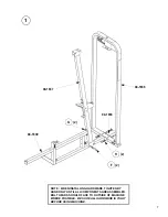
Page 8: ...NG HARDWARE TIGHTEN BY HAND ONLY UNTIL ALL COMPONENTS ARE ASSEMBLED BOLT HEADS SHOULD FACE TO OUTSIDE OF MACHINE WHERE POSSIBLE BE SURE ALL HARDWARE IS TIGHT BEFORE USING MACHINE 04 1836 04 1839 04 18...

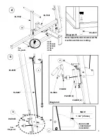
Page 9: ...8 2 04 1840 F 2 G 2 Diagram A V 4 06 0430 2 03 0681 2 05 0492 04 1843 MAKE SURE NUT IS TIGHT 13 0211 3 R 5 06 0025 6 02 1928 2 L To Weight Stack See Diagram A...

Page 10: ...gram C V 4 03 0681 2 06 0430 2 04 1844 05 0492 Diagram B 06 0431 1 3 8 35mm MAX MAKE SURE LOCKING NUT IS SECURE 04 1842 See Diagram B D 04 1841 4 C 451 C 955A 2 C 754B 2 C 766A C 955 Note Adjust thumb...

Page 11: ...IGHT STACK INSTALLATION Review the equipment order to determine the weight stack configuration The boxes are marked with the quantity and weight of the plates 250lb 16 x 15lb plates Qty 5 Box B1603 17...

Page 12: ...ULD THE CAP PLATE OR WEIGHT STACK BE PINNED IN AN ELEVATED POSITION 06 0547 2 C 757 2 WEIGHT 01 2638 2 10 0273 NOTE IF INSTALLING THE WEIGHT SHROUD OPTION REFER TO THE INSTALLATION INSTRUCTIONS PROVID...

Page 13: ...TE 10 0273 10 0274 UP TO PULLEY HOUSING TO SET THE CORRECT GUIDE ROD AND BRACKET SPACING NOW COM PLETELY TIGHTEN HARDWARE CAP PLATE SHOULD MOVE SMOOTHLY ALONG GUIDE RODS IF NOT LOOSEN HARDWARE AND RES...

Page 14: ...label with the top edge of the weights and the side of the label with the outside edge of the pin hole in the weights 4 Verify that the label strip is straight and then remove the liner As the liner...

Page 15: ...ING Read all of the warnings and obtain instruction on 3 Keep body and clothing clear of all moving parts DO NOT wear anything 4 Inspect the machine before use DO NOT use it if it appears damaged DO N...

Page 16: ...LITY IS LIMITED TO ONE YEAR DURATION FROM THE DATE OF DELIVERY TO THE ORIGI NAL PURCHASER SOME STATES DO NOT ALLOW LIMITATIONS ON HOW LONG AN IMPLIED WARRANTY LASTS SO THE ABOVE LIMITATION MAY NOT APP...

Reviews: