background image

7

IMPORTANT

Preventative maintenance is crucial to maintaining the function and safety of this equipment. Your 
facility must establish written guidelines for preventative maintenance and keep written or online 
records of the maintenance performed on these products. As a minimum, the items presented in 
the SAFETY section of this document and the items that follow here, should be included in your 
maintenance program. 

1.  Cables: Inspect end fittings daily for wear. Inspect the entire length of the cable weekly. 

Replace cables at the first sign of wear and on an annual basis. If the cable tension has 
been adjusted, be certain that the cable nut is tight.

2.  Nuts, Bolts, and Fasteners: Check tightness weekly. If any hardware has become loose, 

retighten and/or use Loctite

TM

 brand Threadlocker 242. Be sure all hardware is tight 

before using the machine.

3.  Safety Catches: Inspect catches, stop rods and their associated fasteners weekly. Tighten 

any loose hardware and replace any components at first signs of wear.

4.  Frames: Wipe all machines down with a damp cloth and dry completely each day. This 

includes painted parts, chrome parts and upholstered pads.

5.  Painted and chrome plated parts: Use Simple Green or similar cleaner for light dirt and 

grime. Use Turtle Wax Polishing Compound or a good car polish to remove heavier dirt 
and grease as well as for polishing. DO NOT use solvents, lacquer thinner, acetone or 
finger nail polish remover. For scuffs and marks that are not removed by the above 
methods use a soft scrub cleanser. Make sure all parts are dry upon completion.

6.  Weight stack enclosures (shrouds): Wipe down with a damp cloth as needed.
7.  Exercise instruction labels: Clean with soap and water as needed.
8.  Guide rods: Wipe all dirt and dust from the guide rods before applying a light application 

of Tri-Flow

TM

 or other teflon spray lubricant. Spray the Tri-Flow

TM

 on a rag and then wipe 

the guide rods with the rag. DO NOT use oil lubricants such as WD-40. Caution: Tri-Flow

TM


will stain carpet and clothing.

9.  Bronze bushings: Check monthly for signs of wear and replace as needed.
10.  Linear Bearing Shafts: Wipe any accumulation of dust or other contaminants from the 

shafts on a weekly basis. Apply a thin layer of a Teflon

®

 (PTFE) grease on a weekly basis. 

Paramount recommends Magnalube

®

 brand.

11.  When replacing any component, use only Paramount supplied parts.
12.  Please refer to the General Maintenance Manual (part number: AM-GMM) for other 

important safety and maintenance information.

13.  Be sure all hardware is tight before using the machine.

Retain these instructions for future reference.

If you have any questions, do not hesitate to contact your Paramount dealer or Paramount Fitness 
Corp. at (800)721-2121 or nasales@paramountfitness.com.

G

ENERAL

 C

ARE


AND

 M

AINTENANCE

Summary of Contents for FS-100

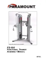
Page 1: ...FS 100 FUNCTIONAL TRAINER ASSEMBLY MANUAL Shown with optional accessory handle kit AM FS 100 REV 072914...

Page 2: ...at nasales paramountfitness com Thank You for your patronage Paramount Fitness Corporation 6450 East Bandini Blvd Los Angeles CA 90040 IMPORTANT SERIOUS INJURIES TO USERS BYSTANDERS OR INSTALLERS CAN...

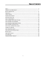
Page 3: ...EMBLE THE ADJUSTMENT COLUMN 15 STEP 3 ASSEMBLE THE CROSS BRACES 16 STEP 4 ASSEMBLE THE REAR SHROUD PANELS 17 STEP 5 ASSEMBLE THE WEIGHT PLATES 18 STEP 6 ATTACH THE WEIGHT STACK LABELS 19 CABLE ROUTING...

Page 4: ...equipment Adults should closely supervise use by teenagers 8 It is recommended that users receive a thorough medical exam before commencing an exercise program All medical issues should be reviewed t...

Page 5: ...is piece of equipment for safe access and operation Installation must meet ADA requirements for accessibility 3 Install this piece of equipment on a solid level surface that does not deviate more then...

Page 6: ...and engaged Verify that the exercise is performed smoothly free of noise and or binding If equipped with a weight stack verify that the proper weight selector pin is in place 3 Check the function of y...

Page 7: ...ood car polish to remove heavier dirt and grease as well as for polishing DO NOT use solvents lacquer thinner acetone or finger nail polish remover For scuffs and marks that are not removed by the abo...

Page 8: ...ional 1 1 ratio machine 13 weight stack settings 5 lbs 65 lbs Pull force increments are 5 0lbs 2 3 kg 65 lb 29 5 kg max resistance at cable end per handle Cable travel is 8 feet 96 inches 244 cm per h...

Page 9: ...wo people are used to assemble this machine Ratchet Handle 3 8 socket or wrench 7 16 socket 9 16 socket 7 32 or 5 5mm Hex Bit Socket 3 8 wrench or socket 7 16 wrench 9 16 wrench 19mm 3 4 wrench or adj...

Page 10: ...ROD 2 5 FS100 CLM001 ADJUSTMENT COLUMN CHROME 1 6 FS100 RSH000X SHROUD PANEL ASSEMBLY REAR 1 7 FS100 SHD001 SHROUD SIDE PANEL METAL 2 8 FS100 FSLL0X FRONT SHROUD ASSY LEFT SIDE FRAME LEFT PANEL 1 9 F...

Page 11: ...MBLY 1 4 FS100 GDR001 GUIDE ROD 2 5 FS100 CLM001 ADJUSTMENT COLUMN CHROME 1 6 FS100 RSH000X SHROUD PANEL ASSEMBLY REAR 1 7 FS100 SHD001 SHROUD SIDE PANEL METAL 2 8 FS100 FSRL0X FRONT SHROUD ASSY RIGHT...

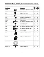
Page 12: ...Screw 10 32 X 1 2 28 56 C 900A Flat Washer 10 40 80 C 900D Lock Nut 10 32 12 24 C 416 Hex Head Screw 1 4 20 x 2 1 4 ZINC 4 8 C 752 Flat Washer 1 4 SAE 8 16 C 740 Lock Nut 1 4 20 4 8 C 448 Hex Head Scr...

Page 13: ...l Weight Stack 12 position 65 lbs with 29 5 kg 1 2 B1005 Carabiner snap link 1 2 B1110A Strap Handle 1 2 PART NUMBER DESCRIPTION QTY BOX QTY MACHINE OPTIONAL ACCESSORY KIT An optional accessory kit is...

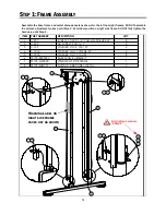
Page 14: ...until Step 2 Note label position on right side frame DO NOT fully tighten the hardware until Step 2 STEP 1 FRAME ASSEMBLY 7 0 3 57 180 5 6 5 37 21 47 6 5 3 1 3 36 3 6 5 6 5 2 3 6 5 7 6 3 6 5 7 866 6 5...

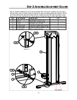
Page 15: ...are The left side is shown below The right side is similar with the exception being that the pulley housing is a mirror image of the left side Fully tighten all of the hardware including the frame har...

Page 16: ...e 3 Verify that all 4 feet of the machine are sitting on the floor Incrementally tighten the hardware on all of the braces and chin up bar It may help to shake the machine as you tighten the hardware...

Page 17: ...17 STEP 4 ASSEMBLE THE REAR SHROUD PANELS 7 0 3 57 180 5 6 5 37 21 47 6LGH 47 0DFKLQH 2 187 1 16 0 187 6 5 3 1 3 36 3 6 5 7 866 6 56 6 528 3 1 66 0 5 5 6 6 6 528 1 3 7...

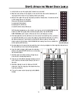
Page 18: ...as shown below 3 Tilt the guide rods forward and install the washers bumpers weight plates 12 plates per side 4 Install the top plate selector bar 5 Slide the guide rods between the two upper frame p...

Page 19: ...emove the backing strip directly behind the area of the LB stickers Likewise if you intend to install the KG stickers remove the backing directly under the KG stickers DO NOT REMOVE the backing from t...

Page 20: ...ROUTING DIAGRAM LQ PP Correct Wrong Wrong Correct DO NOT EXCEED THIS DIMENSION ENSURE THAT THE CABLE IS NOT ROUTED ON THE OUTSIDE OF THE CABLE RETAINER PIN TYPICAL 3 PULLEYS Cable Retainer Pin Cable...

Page 21: ...21 STEP 7 CABLE INSTALLATION 7 0 3 57 180 5 6 5 37 21 47 6 47 0 1 38 5229 38 59 6 5 6 5 6 5 7 6 3 2 187 1 16 0 187 6 66 6 3 8 6 3 38 75 9 6723...

Page 22: ...16 0 187 6 5 3 1 3 36 3 6 5 7 866 6 65 5217 6 528 66 5 7 6 5 0 7 3 1 6 655 5217 6 528 66 5 7 6 5 0 5 7 3 1 6 6 6 528 1 3 7 7 0 3 57 180 5 6 5 37 21 HIW 6LGH 47 2 187 1 16 0 187 6 5 3 1 3 36 3 6 5 7 86...

Page 23: ...U ARE UNSURE ON HOW TO USE A MACHINE SEEK THE ASSISTANCE OF OUR FLOOR PERSONNEL WE WILL BE HAPPY TO INSTRUCT YOU ON HOW TO USE THE EQUIPMENT PROPERLY IMMEDIATELY REPORT ANY PIECE OF EQUIPMENT THAT IS...

Page 24: ...of the guide rods with a Teflon PTFE spray lubricant Paramount recommends using TriFlowTM brand for excellent results 3 On the vertical columns verify that the adjustment pins in the pulley housings f...

Page 25: ...0 3 57 180 5 6 5 37 21 47 61 3 22 1 1 1 21 675 3 7 2 2 6 5 3 6 5 3 2 3 7 6 5 2 3 6 5 7 6 3 6 5 0 17 5266 5 2 5 6 5 66 0 833 5 5266 5 6 5 1 83 5 6 6 66 5 0 7 6 6 56 66 5 0 5 7 6 6 0 7 67 6 5 7 6 5 180...

Page 26: ...2 187 1 16 0 187 6 5 7 866 6 5 6 5 0 66 0 6 66 0 6 0 520 8670 17 2 801 6 6 5217 6 528 66 7 6 5 0 7 3 1 6 6 5 5217 6 528 66 7 6 5 0 5 7 3 1 6 5 8 52 6 0 5 0 17 6 5 0 6 3 38 286 1 66 0 7 6 3 8 6 3 38 75...

Page 27: ...27 PARTS DIAGRAMS...

Page 28: ...16 0 187 6 5 7 866 6 5 6 5 0 66 0 6 66 6 0 520 8670 17 2 801 6 65 5217 6 528 66 5 7 6 5 0 7 3 1 6 655 5217 6 528 66 5 7 6 5 0 5 7 3 1 6 5 8 52 6 0 5 0 17 6 5 0 6 3 8 6 3 38 75 9 6723 6 3 38 286 1 66...

Page 29: ...29 PARTS DIAGRAMS...

Page 30: ...3 57 180 5 6 5 37 21 47 6 5 0 17 6 5 0 5 1 3 8 5 75 29 20 5 3 7 227 39 25 00 57 29 5 1 3 8 25 00 2 6 73 723 3 7 38 286 1 66 0 7 0 3 57 180 5 6 5 37 21 47 6 73 723 3 7 6 725 5 66 6 3 0 17 723 3 7 38 28...

Page 31: ...187 0 1 16 57 3 6 5 7 0 3 6 38 286 1 3 927 6 3 0 17 38 286 1 8670 17 7 6 3 6 9 38 286 1 66 0 6 3 1 323 3 1 66 0 6 3 38 286 1 66 0 5 7 7 0 3 57 180 5 6 5 37 21 47 51 1 1 163 7 21 51 1 203 7 16 57 3 1 6...

Page 32: ...32 PARTS DIAGRAMS 2 2 6 56 5 5 6 528 6 6 5 7 5 0 5 7 6 528 3 1 6 6 7 5 0 7 6 528 3 1 6 65 5 7 5 0 7 6 528 3 1 35 6 5 35 6 5 35 6 55 35 6 6 655 5 7 5 0 5 7 6 528 3 1...

Page 33: ...ot authorized by Paramount or any damage caused by improper handling natural disasters acts of God or servicing by non Authorized Dealers This includes but is not limited to the relocation of the prod...

Page 34: ...NOTES...

Page 35: ......

Page 36: ...Paramount Fitness Corporation 6450 E Bandini Blvd Los Angeles CA 90040 3185 Phone 1 323 721 2121 Fax 323 724 2000 1 800 721 2121 www paramountfitness com...

Reviews: