

27
M
ACHINE
L
ABELS
WARNING
!
MAXIMUM
B2141C
B2141C
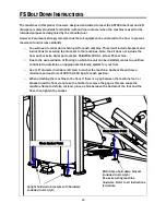
WARNING
SERIOUS INJURY CAN OCCUR ON
ASTM F1749
P/N B2065
THIS EQUIPMENT IF THE PIN IS NOT
!
B2065
If this machine is to be installed in a
public use facility, ASTM F1749
requirements specify that the facility
sign shown to the right is to be
installed in plain view.
If you did not receive the facility sign
with your order, you can obtain one
free of charge from Paramount by
calling 1-800-721-2121.
BE ALERT!
THE FITNESS EQUIPMENT IN THIS FACILITY
PRESENTS HAZARDS WHICH, IF NOT AVOIDED,
COULD CAUSE SERIOUS INJURY OR DEATH.
PRIOR TO USING THE EQUIPMENT, READ THE WARNING LABELS
AND INSTRUCTION PLACARDS AFFIXED TO EACH MACHINE.
IF YOU ARE UNSURE ON HOW TO USE A MACHINE, SEEK THE
ASSISTANCE OF OUR FLOOR PERSONNEL. WE WILL BE HAPPY
TO INSTRUCT YOU ON HOW TO USE THE EQUIPMENT PROPERLY.
IMMEDIATELY REPORT ANY PIECE OF EQUIPMENT THAT IS NOT
FUNCTIONING PROPERLY TO OUR FLOOR PERSONNEL SO THAT
IT MAY BE EVALUATED AND SERVICED PROMPTLY.
DO NOT ATTEMPT TO USE OR FIX ANY PIECE OF EQUIPMENT
THAT IS NOT FUNCTIONING PROPERLY
ASTM F1749-96
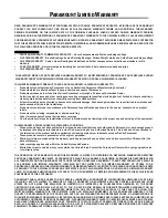
WARNING
SERIOUS INJURY CAN OCCUR
P/N B2051
!
B2051
COMPLETELY INSERTED BEFORE USE.
ON THIS EQUIPMENT IF THE
CABLES AND THEIR ATTACH-
MENT COMPONENTS ARE NOT
INSPECTED OFTEN. REPLACE
AT FIRST SIGNS OF WEAR.
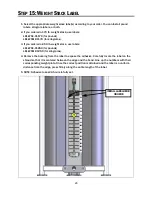
Height Under Nut
to Bolt Head.
MAKE SURE
locking nut is tight.
MAX
1”
LBL-WSE-01170 (170 LB)
LBL-WRN-0002
LBL-PR-FS51
LBL-WSE-01250 (250 LB)
LBL-WSM-01170 (77 KG)
LBL-WSM-01250 (114 KG)
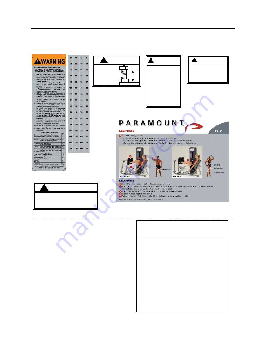
WARNING
LBL-WRN-0004
!
LBL-WRN-0004
WHEN DOING
CALF RAISES,
ALWAYS
ADJUST
THE FOOT
PLATE TO THE
FURTHEST
POSITION
POSSIBLE
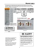
The following are the Warning labels required for this FS machine. If any of these
labels are missing or become damaged, Paramount will replace them free of charge.
Note: these labels are not to scale.
Summary of Contents for FS-51
Page 1: ...FS 51 LEG PRESS ASSEMBLY MANUAL AM FS51 010913...
Page 31: ......


