background image

23

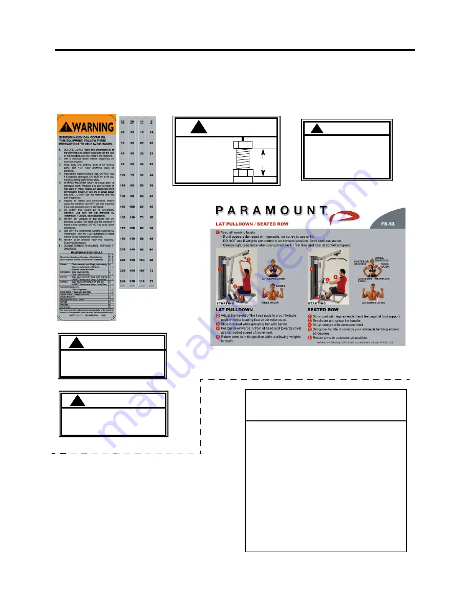
M

ACHINE

 L

ABELS

WARNING

!

MAXIMUM

B2141C

B2141C

WARNING

 SERIOUS INJURY CAN OCCUR ON 

ASTM F1749

P/N B2065

 THIS EQUIPMENT IF THE PIN IS NOT

!

B2065

If this machine is to be installed in a 
public use facility, ASTM F1749 
requirements specify that the facility 
sign shown to the right is to be 
installed in plain view.

If you did not receive the facility sign 
with your order, you can obtain one 
free of charge from Paramount by 
calling 1-800-721-2121.

BE ALERT!

THE FITNESS EQUIPMENT IN THIS FACILITY

PRESENTS HAZARDS WHICH, IF NOT AVOIDED,

COULD CAUSE SERIOUS INJURY OR DEATH.

PRIOR TO USING THE EQUIPMENT, READ THE WARNING LABELS
AND INSTRUCTION PLACARDS AFFIXED TO EACH MACHINE.

IF YOU ARE UNSURE ON HOW TO USE A MACHINE, SEEK THE
ASSISTANCE OF OUR FLOOR PERSONNEL. WE WILL BE HAPPY
TO INSTRUCT YOU ON HOW TO USE THE EQUIPMENT PROPERLY.

IMMEDIATELY REPORT ANY PIECE OF EQUIPMENT THAT IS NOT 
FUCTIONING PROPERLY TO OUR FLOOR PERSONNEL SO THAT
IT MAY BE EVALUATED AND SERVICED PROMPTLY.

DO NOT ATTEMPT TO USE OR FIX ANY PIECE OF EQUIPMENT
THAT IS NOT FUNCTIONING PROPERLY

ASTM F1749-96

WARNING

 SERIOUS INJURY CAN OCCUR

P/N B2051

!

B2051

COMPLETELY INSERTED BEFORE USE.

ON THIS EQUIPMENT IF THE

CABLES AND THEIR ATTACH-

MENT COMPONENTS ARE NOT

INSPECTED OFTEN. REPLACE

AT FIRST SIGNS OF WEAR.

Height Under Nut

to Bolt Head.

MAKE SURE

locking nut is tight.

MAX

1”

LBL-WSE-01170 (170 LB)

LBL-WRN-0002

LBL-PR-FS53

LBL-WSE-01250 (250 LB)

LBL-WSM-01170 (77 KG)
LBL-WSM-01250 (114 KG)

LBL-WRN-0003

LBL-WRN-0003

WARNING

USE THIS LAT BAR ON PARAMOUNT LAT STATIONS WITH 250 LBS


!

OR LESS. INSPECT CABLE FITTING AND CONNECTIONS PRIOR TO 
USE. BE CERTAIN THAT THE CONNECTIONS ARE SECURE. FAILURE 
TO FOLLOW THESE PROCEDURES MAY RESULT IN SERIOUS 
INJURY.

Summary of Contents for FS-53

Page 1: ...FS 53 LAT ROW ASSEMBLY MANUAL AM FS53...

Page 2: ...ealer or by contacting a Paramount Customer Service Representative at 1 800 721 2121 or 1 323 721 2121 Office hours are Monday Friday 7 30 am 4 30 pm PST Or email us at nasales paramountfitness com Th...

Page 3: ...SSEMBLE THE MAIN FRAME 10 STEP 2 ASSEMBLE WEIGHT STACK LAT TUBE 12 STEP 3 ASSEMBLE FRONT SHROUD ROW TUBE FOOT FRAME 14 STEP 4 ASSEMBLE ROW CABLE ROW TUBE SUPPORT 17 STEP 5 INSTALL LAT BAR ROW HANDLE 1...

Page 4: ...ustable arms Make sure that the selector pin inserts completely into each position without binding 10 DO NOT attempt to free any jammed assemblies by yourself as this may cause injury 11 DO NOT use ad...

Page 5: ...ods Wipe all dirt and dust from the guide rods before applying a light application of Tri FlowTM or other teflon spray lubricant Spray the Tri FlowTM on a rag and then wipe the guide rods with the rag...

Page 6: ...3 3 4 WEIGHT STACK CONFIGURATION MACHINE WEIGHT APPROXIMATE FLOOR LOADING 170 lbs 454 LBS 206 KG 53 LBS FT2 257 KG M2 250 lbs 534 LBS 242 KG 62 LBS FT2 303 KG M2 MACHINE WEIGHT AND FLOOR LOADING IN US...

Page 7: ...5 Use this table to measure bolts and set collar spacing Weight Plate Cartons Depending upon your order this machine can be assembled with either a 170 lb or 250 lb weight stack For a 170 lb weight st...

Page 8: ...0X TOP CAP 1 2 FS53 SHD 300X FRONT SHROUD 1 3 FS SHD 350X REAR SHROUD 1 4 FS53 UPR 000X UPRIGHT 1 5 FS53 GRD 300X GUIDE ROD 2 6 FS53 PAD 100X SEAT PAD 1 7 FS BKT 000 GUIDE ROD BRACKET 2 8 FS PAD 400X...

Page 9: ...0X FLOATING PULLEY SET 1 5 FS53 SFR 100X FOOT FRAME 1 6 FS53 SFR 200X FOOT PLATE 2 7 FS53 SFR 300X SEAT FRAME 1 8 FS53 SFR 400X THIGH FRAME 1 9 FS BAR 100X LAT BAR 1 10 FS BAR 200X ROW HANDLE 1 11 FS5...

Page 10: ...MBER DESCRIPTION QTY 1 FS53 UPR 000X UPRIGHT FRAME 1 2 FS53 SFR 300X SEAT FRAME 1 3 FS53 SFR 400X THIGH FRME 1 4 FS53 PAD 100X SEAT PAD 1 5 FS PAD 400X THIGH ROLLER PAD 2 6 S 550 FOOT MOLDED 4 7 C 965...

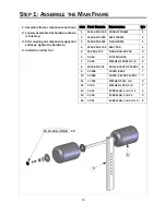
Page 11: ...11 STEP 1 ASSEMBLE THE MAIN FRAME 10 14 12 9 11 X 3 10 15 9 12 11 X 2 1 2 4 DETAIL A DETAIL B A B...

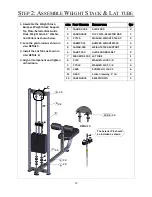
Page 12: ...iew DETAIL C 3 Install the Lat Tube as shown in view DETAIL D 4 Align all component and tighten all hardware ITEM PART NUMBER DESCRIPTION QTY 1 FS GRD 300X GUIDE ROD 2 2 FS SBR 000X TOP PLATE SELECTOR...

Page 13: ...ACK LAT TUBE 10 8 9 X 4 Set the distance between the Collars and the tube as shown 1 distance from the bottom of the bolt to the top of the bar as shown Lock the nut after the distance is set D DETAIL...

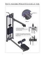
Page 14: ...455 SCREW HH 3 8 X 4 4 1 Install the front Shroud first Slide the top protion of the shroud up to the Lat Tube from the side and push the lower portion of the shroud into the Upright 2 Install the Ro...

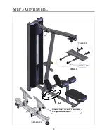
Page 15: ...15 STEP 3 CONTINUED 6 12 5 7 X 2 7 5 9 6 X 2 6 13 8 5 7 X 2 7 5 9 6 X 2 2 F DETAIL F DETAIL G G...

Page 16: ...16 STEP 3 CONTINUED 6 13 8 5 7 X 2 7 5 9 6 X 2 6 11 8 5 X 4 Slide Foot Plate on to the Foot Frame and tighten all hardware H DETAIL H...

Page 17: ...900 PULLEY 4 5 2 5 FS BSH 101 PULLEY BUSHING 3 8 2 6 C 749 WASHER LOCK 3 8 6 7 C 745C WASHER FLAT 3 8 12 8 C 955A COVER BASE 16 9 C 955S COVER SILVER 16 10 C 443 SCREW HH 3 8 x 5 8 2 11 C 460 SCREW HH...

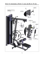
Page 18: ...8 STEP 4 ASSEMBLE ROW CABLE ROW TUBE 9 16 8 7 9 13 8 7 17 4 9 12 8 6 X 2 9 16 8 7 5 9 16 8 7 9 12 8 6 X 2 3 X 2 2 X 2 4 9 14 8 7 5 9 15 8 7 18 DETAIL M M N DETAIL N 1 Adjust stop to remove cable slack...

Page 19: ...STEP 5 INSTALL LAT BAR ROW HANDLE 1 Install the Lat Bar and Row Handle as shown below 1 3 2 3 ITEM PART NUMBER DESCRIPTION QTY 1 FS BAR 100X LAT BAR 1 2 FS BAR 200X ROW HANDLE 1 3 B 1004 1 4 QUICK LIN...

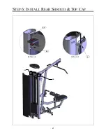
Page 20: ...shroud into the upright 2 Install the Top Cap on the upright as shown in view DETAIL AF 6 7 1 2 ITEM PART NUMBER DESCRIPTION QTY 1 FS SHD 350X REAR SHROUD 1 2 FS CAP 000X TOP CAP 1 3 C 754C WASHER FL...

Page 21: ...21 STEP 6 INSTALL REAR SHROUD TOP CAP 7 7 4 3 6 5 3...

Page 22: ...E 01250 for pounds LBL WSM 01250 for kilograms 4 Remove the backing from the label to expose the adhesive Carefully locate the label on the shroud so that it is centered between the edge and the bend...

Page 23: ...EL WE WILL BE HAPPY TO INSTRUCT YOU ON HOW TO USE THE EQUIPMENT PROPERLY IMMEDIATELY REPORT ANY PIECE OF EQUIPMENT THAT IS NOT FUCTIONING PROPERLY TO OUR FLOOR PERSONNEL SO THAT IT MAY BE EVALUATED AN...

Page 24: ...th a teflon spray lubricant Paramount recommends using TriFlowTM brand 2 Adjust the thigh pad through each position Verify that the adjustment pin insert freely into each position and is fully engaged...

Page 25: ...25 NOTES...

Page 26: ...LIMITED TO THE IMPLIED WARRANTY OF FITNESS FOR A PARTICULAR PURPOSE AND THE IMPLIED WARRANTY OF MERCHANTABILITY IS LIMITED TO ONE YEAR DURATION FROM THE DATE OF DELIVERY TO THE ORIGINAL PURCHASER SOME...

Page 27: ......

Page 28: ...Paramount Fitness Corporation 6450 E Bandini Blvd Los Angeles CA 90040 3185 Phone 1 323 721 2121 Fax 323 724 2000 1 800 721 2121 www paramountfitness com AM FS53 071207 fm REV 7 16 07...

Reviews: