18
S
TEP
5: A
SSEMBLE
C
ABLE
& P
ULLEYS
$
%
&
'
(
12
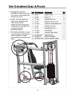
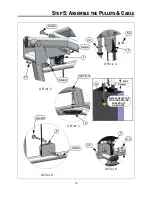
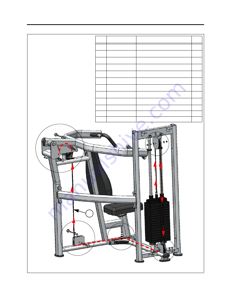
1. Starting at the top plate,
assemble the cable and selector
pin as shown. Install pulleys and
hardware as you go.
2. Tighten the cable adjustment
bolt to remove slack from the
cable. Ensure that the
adjustment bolt is inserted into
the selector bar according to the
minimum dimension
specification shown.
3. After tightening hardware, slowly
cycle the machine. Verify that the
cable is seated in the pulley
groves and that each pulley turns
freely.
ITEM
P
ART
N
UMBER
D
ESCRIPTION
Q
TY
1
B 900
PULLEY, 4-1/2”
4
2
B 898
PULLEY, 6”
1
3
C 754C
WASHER, FLAT, 3/8
10
4
C 448
SCREW, HH, 3/8 X 1-3/4”
4
5
C 766A
LOCK NUT, NYLON INSERT JAM
5
6
C 453
SCREW, HH, 3/8 X 2”
1
7
C 749
WASHER, LOCK 3/8
1
8
C 955A
COVER, BASE
6
9
C 955S
COVER, SILVER PLASTIC
6
10
FS-SPN-000X
SELECTOR PIN
1
11
FS562100
SCREW, SHOULDER
1
12
FS65-CBL-000X
CABLE, SHOULDER PRESS
1


