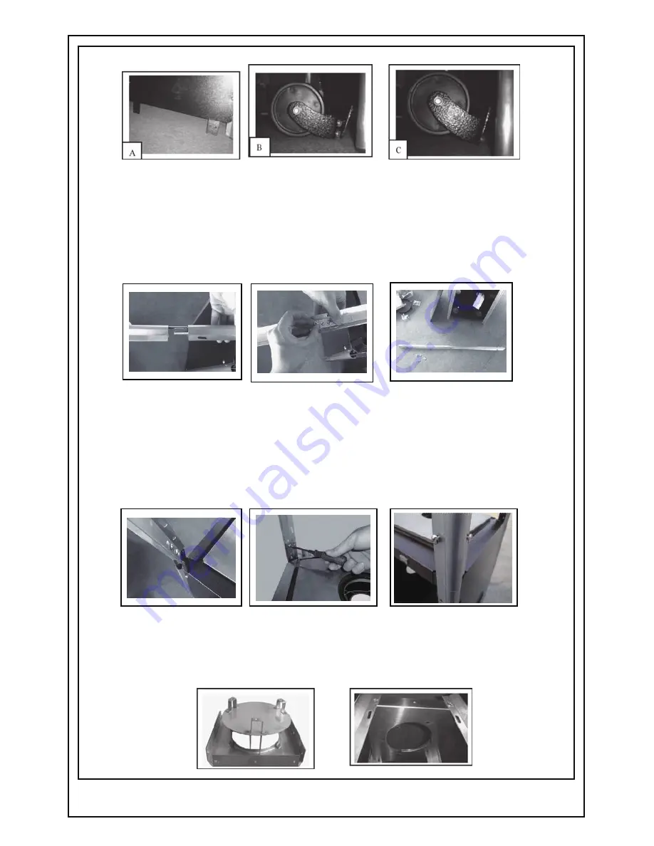
STEP 4:
Locate the Aluminum Tubes (4). Remove 8 pieces/4 sets of tubes. There will
be 4 pieces of tubes that have a rod protruding from one end and 4 pieces of tubes
WITHOUT the protrusion. To fit tubes together, locate the piece WITHOUT the
protrusion and make sure there is a small hole at the bottom of the tube. Then locate a
tube WITH the protrusion and slide the protruding rod into the end of the other tube
until the two holes align. Insert one M3/16 screw (14) through the aligned hole and one
screw into the bottom piece of the rod and tighten to secure the two rods together.
Repeat this with the other 3 sets (4 sets total, 8 – M3/16 screws total).
STEP 5:
Once you have the assembled sets of the Aluminum Tubes, slide the bottom of
the assembled set (note that the bottom will have 3 holes—top has NO holes) down
over the protruding rod located at each corner of the Tank Housing Assembly (1) and
secure the assembled rod set to the heater on the inside of the rod by using 2 - M3/16
screws (14) on each corner (4 corners total, 8 - M3/16 screws total). Then secure the
assembled rod set to the heater on the outside of the rod by using 2 – M3/16 screws (4
corners total, 8 – M3/16 screws total).
STEP 6:
Locate the Damper (5). Attach the Damper (5) to the top of the assembled
Aluminum Tubes using 2 – M3/16 screws (14) on each corner (4 corners total, 8 –
M3/16 screws total).
- 8 -
Summary of Contents for PH08-S BK
Page 9: ......


