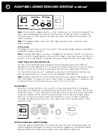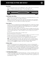
Power Button
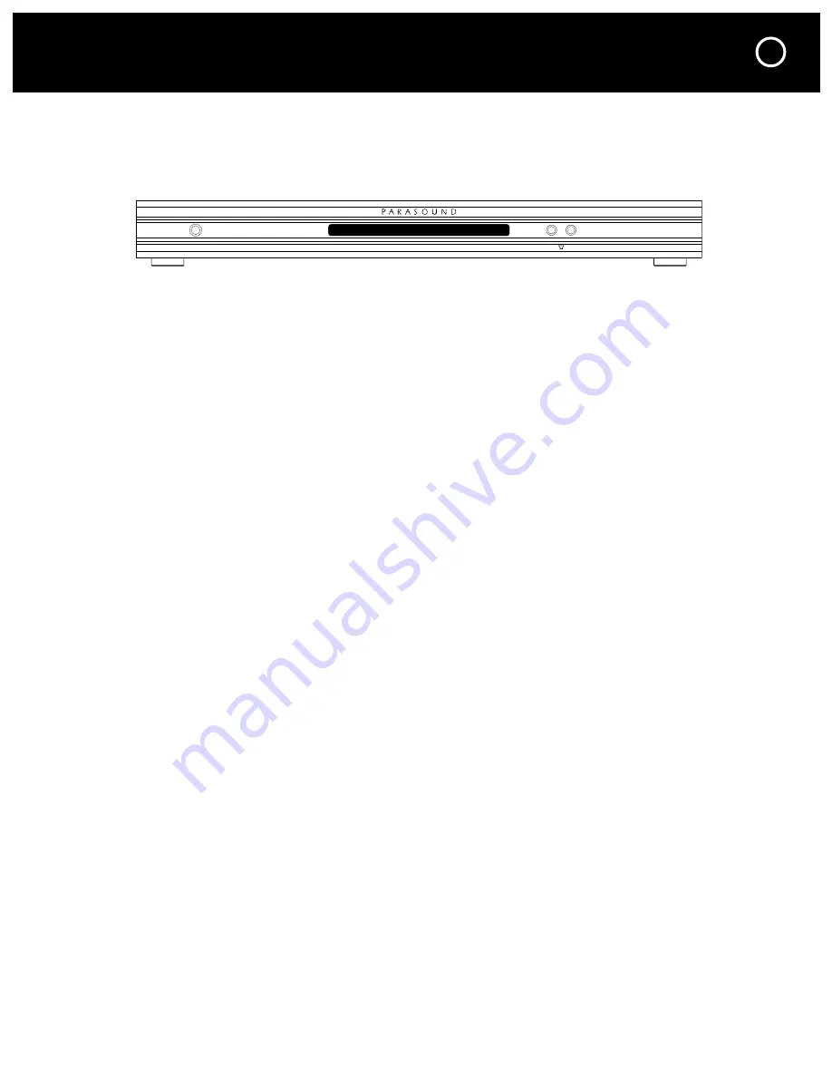
Press the Power button once to turn the Model 275 on, press it again to turn it off. The Power
button is inoperative when the Auto Turn On switch is set to Audio or 12V.
Note:
It is normal for the 275 Protect indicator to flash briefly right after turn on.
A and B Speaker Select Buttons
These buttons turn on the speaker pairs connected to the corresponding Speaker Pair A and B
terminals. They will also select two single mono speakers.
Note:
The front panel buttons and switches activate relays which perform the actual speaker
switching. The contacts in the relays will last longer if you don’t press the A and B buttons to
turn speaker pairs on and off while the 275 is playing at high volume.
Protect Indicator
The Protect indicator will illuminate red if the Model 275 experiences an external fault condition
and the unit will stop playing. This prevents possible damage to the unit from continued opera-
tion. Examples of external fault conditions are short circuited speaker wires, excessive heat,
and trying to drive too many speakers at high levels.
If Protect is illuminated you need to locate and correct the fault; for example, remove the short
circuit, let the unit cool down, check the load impedance and the setting of the Load Impedance
switch, lower the volume level. To reset the protection circuit you need to turn the unit off.
Turning it off:
•
Auto Turn On switch (on the rear panel) in the Man position:
press the Power button on the front panel.
•
Auto Turn On switch in the 12V position: turn off the 12V trigger source; the 275 will turn itself
off right away. You can also turn it off by unplugging its AC power cord.
•
Auto Turn On switch in the Audio position: turn off the preamplifier, surround controller or
system controller that drives your 275. You can also unplug the 275’s AC power cord.
Note:
It requires approximately 15 minutes after removing the audio source before the 275
turns itself off. If you don’t want to wait and you have access to its AC cord, simply unplug it.
Leave it off and/or unplugged for awhile to cool down and you’re confident the fault is
corrected. If you unplugged its AC power cord to turn it off, plug it in again.
Hi-Temp Indicator
Hi-Temp will illuminate red when the Model 275 exceeds its maximum safe operating tem-
perature. If the heat persists, the unit will activate its protection circuit and stop playing. It will
remain in this protection mode until the temperature drops and the unit is turned off to reset
its protection circuit. Use the same turn-off procedure as above. If Hi-Temp appears, it’s likely
the unit is been over-driven at too high a listening level or is attempting to drive a speaker load
impedance that is too low. It’s probable the unit has not been provided with sufficient ventila-
tion. These conditions must be corrected before turning it on again to resume operation.
L and R Channel Status Indicators
L and R will illuminate green when the Model 275 power is on and it is operating normally. The
L indicator will not light if a fault is only in the left channel; the R indicator will not light if a fault
is only in the right channel. Neither L or R indicators will illuminate if there is a general fault or if
the temperature is too high.
FRONT PANEL BUTTONS AND DISPLAY
9
A
B
M o d e l 2 7 5 T w o C h a n n e l A m p l i f i e r
Power
Protect
Hi Temp
L
R


