background image

8

CONNECTING YOUR P 7: AUDIO OUTPUT CONNECTIONS

AUDIO OUTPUT CONNECTIONS

There are 2 sets of Main Output jacks, one set with RCA connectors and one set with balanced 
XLR connectors. There is also a fi xed level record output for connecting an audio recorder. Read 
through this section to determine which connections should be used in your setup.

MAIN OUTPUT JACKS 

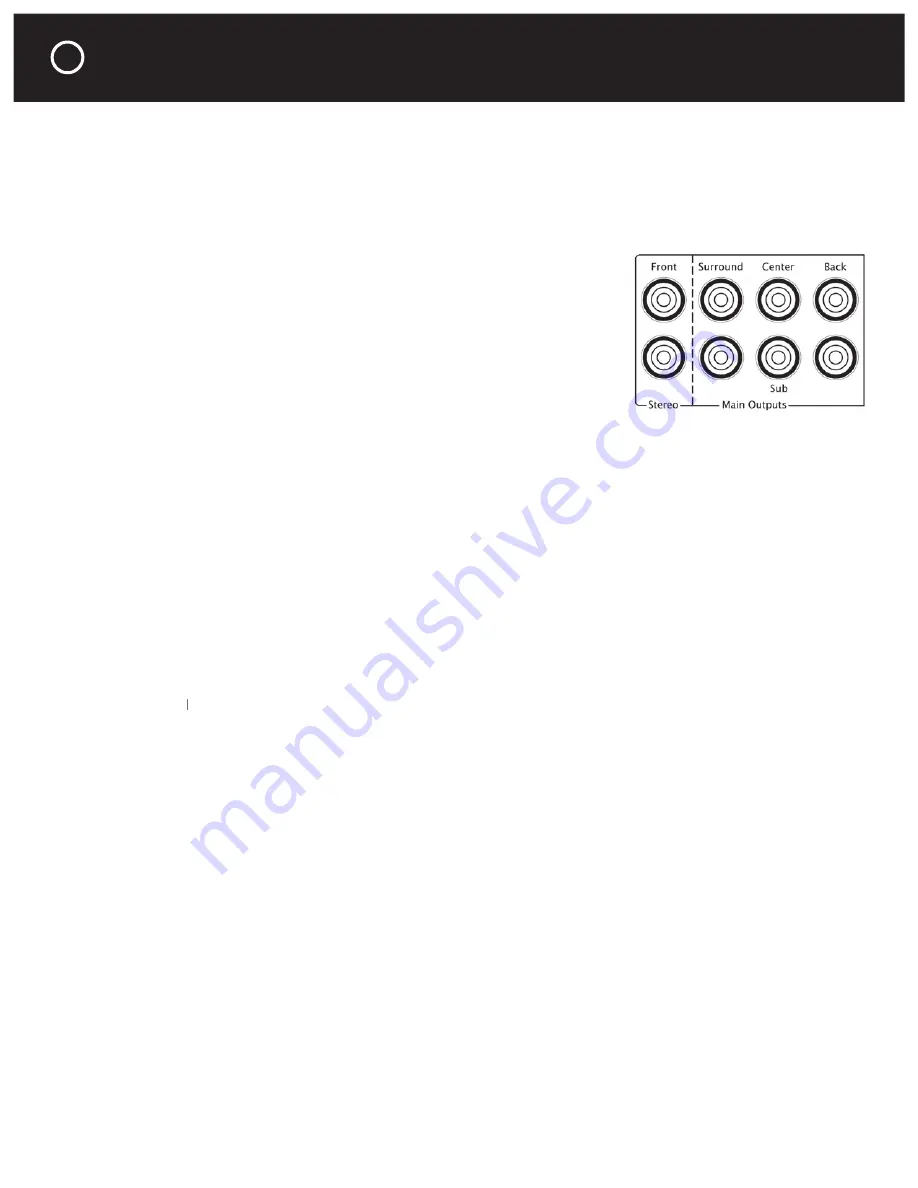
The Main Output jacks connect to the inputs on your power amplifi er(s). 
The P 7 is equipped with both balanced and unbalanced output jacks. 
The balanced and unbalanced output jacks are active simultaneously.
Balanced connections provide superior hum and noise cancellation, 
especially for long cable runs. Many serious listeners also prefer the 
sonic characteristics of balanced interconnects because the lower 
inherent noise fl oor contributes to a more defi ned and spacious 
soundstage. For more information on balanced connections see the 
Frequently Asked Questions section of this manual.

Main Left and Right Output Jacks – for a stereo system

Connect only the Main Output Front Left & Right jacks to your stereo power amplifi er. 

Main Sub Output Jack – for a stereo system with a subwoofer

If your stereo system also includes a subwoofer, you will connect the P 7’s Sub Output jack to 
your subwoofer. The frequency characteristics of the subwoofer output is determined by choices 
you make in the P 7’s setup menu. For more information about the subwoofer output setup see 
page 17.

Main Output Jacks – In a 5.1 or 7.1 Multichannel System 

If you also enjoy surround sound music and movies, you will connect your P 7’s Main Output 
Front Left & Right, Surround L & R, Center & Sub Out jacks to your power amplifi er(s). If you have 
a 7.1 system, you will also connect the Main Output Back L & R jacks.

Note:

 The P 7’s center, surround and back channel outputs reproduce signals only from sources 

Note:

Note:

that are connected to the center, surround and back channel input jacks of the multichannel inputs 
9 and 10. Because it is pure analog the P 7 cannot create surround sound from 2 channel sources.

BASS MANAGEMENT FOR THE LEFT, RIGHT AND SUB OUTPUT JACKS

The P 7 has built-in analog bass management for audio systems which include a subwoofer. The 
bass management for the left, right and subwoofer output jacks has two modes of operation. One 
mode is for the P 7’s stereo inputs (inputs 1-8) and the other mode is for its multichannel inputs 
(inputs 9 & 10). There are two modes of operation to maintain the tonal balance when you switch 
between stereo and multichannel sources.

Mode 1: For Stereo Sources (Inputs 1–8)

When inputs 1 through 8 are selected, the P 7 creates a subwoofer channel output by mixing the 
Left and Right channels then routing the L+R mix through a low-pass crossover. You can select 
the subwoofer crossover frequency in the P 7 Setup menu. If you have small front left and right 
speakers the P 7 also has a high-pass crossover to fi lter out bass frequencies from the Left and 
Right Out jacks. You can select the Left and Right crossover frequency in the P 7 Setup menu. 
For more information about adjusting the bass management settings see page 17.

Mode 2: For Multichannel Sources (inputs 9 & 10)

Inputs 9 & 10 are for the analog multichannel outputs from Blu-ray, HD-DVD, SACD and DVD 
players. These sources provide their own bass management and setup menus. Any subwoofer 
and speaker size/crossover settings should be selected in the source component’s setup menu. 

Summary of Contents for HALO P 7

Page 1: ......

Page 2: ...will only fit into a grounding power outlet If you are unable to insert the plug into the outlet contact your electrician to replace your obsolete outlet Do not defeat the safety purpose of the ground...

Page 3: ...sound warranty service We recommend that you make an extra copy of your original purchase receipt bill of sale and store it inside the P 7 s carton Important Warranty Information There is no Parasound...

Page 4: ...ns on your P 7 10 Using the Bypass Mode With a Surround Receiver Using the Bypass Mode With a Surround Receiver Using the Bypass Mode With a Surround Receiver 11 Making Adjustments in the Setup Menu M...

Page 5: ...t s at least 22 inches wide so you ll be able to turn it around for access to its rear panel connections Ventilation Requirements To reduce the chances of your P 7 overheating please follow these guid...

Page 6: ...shared with the rear panel In 6 jack Phono Input In 1 Phono Stereo The P 7 is equipped with a high quality phono preampli er If you wish to connect a turntable set the Input 1 Phono Cartridge switch...

Page 7: ...l Multichannel input jacks In 9 Multi 1 and In 10 Multi 2 Surround Sound Inputs 9 and 10 are for use with sources equipped with analog outputs for surround sound These sources include many DVD players...

Page 8: ...li er s If you have a 7 1 system you will also connect the Main Output Back L R jacks Note The P 7 s center surround and back channel outputs reproduce signals only from sources Note The P 7 s center...

Page 9: ...and 10 This is useful because you may prefer to have different subwoofer levels for your stereo sources and your multichannel sources TAPE RECORD OUT JACKS The Record Out jacks connect to the record I...

Page 10: ...P 7 s 12V Output jack to the triggered component s trigger input jack using the provided trigger wire with the 2 5 mm sub mini plugs Note Most Parasound Power Ampli ers are equipped with a 2 5 mm 12V...

Page 11: ...rces Because an external power ampli er will be of a higher quality than the ampli er stage built into your surround receiver you will also be getting upgraded sound for all of your digital sources as...

Page 12: ...o the L R Sub jacks of the P 7 s Multichannel Inputs 9 or 10 The Main Outputs from the P 7 will connect to your power ampli er Your Front L R speakers will connect directly to the new 2 channel power...

Page 13: ...n Outputs from the P 7 will connect to your power ampli er s Do not connect any speakers to the speaker terminals on your surround receiver Connect all speakers to your separate power ampli er s inste...

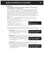
Page 14: ...ector Factory Reset Erase all your Setup menu selections and restore factory defaults Please read the full descriptions in the following pages to determine which functions features are of interest to...

Page 15: ...ti 1 or In 10 Multi 2 to function as bypass inputs This means they will pass the signals from the corresponding 7 1 channel inputs directly to the 7 1 channel output bypassing all P 7 volume tone and...

Page 16: ...he Setup menu Once in the offset setup you can cycle through and compare all the sources by pressing the Enter button on the remote After each input level offset is set all of your sources should play...

Page 17: ...ce devices DVD Blu ray SACD and DVD A players Press the Enter button to proceed into the Bass Management setup Press the VOL Up or VOL Down buttons to change the current setting Press the Enter button...

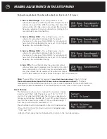
Page 18: ...a stereo input is selected Use this option if you don t have a subwoofer or if you don t want your subwoofer to play when inputs 1 8 are selected The subwoofer output will still be available when the...

Page 19: ...is order None Zhd1 Zhd2 Zhd3 Zhd4 Zhd5 back to None Press the Enter button to change the P 7 input you wish to associate Each press of the Enter button will step to the next P 7 input After you nish p...

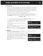
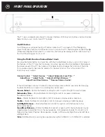
Page 20: ...Bass Adjust Treble Adjust Left Right Balance Adjust Front Rear Balance Resume Volume Control If the Volume Select knob isn t turned to make an adjustment within 5 seconds after pressing the Select bu...

Page 21: ...ubwoofer level trim is adjusted by rst pressing the Enter button and then the Bass Up or Bass Down buttons on the remote There are two independent subwoofer trim memory settings one level setting is f...

Page 22: ...e adjusted when either In 9 Multi 1 or In 10 Multi 2 is selected Note Mute Button Pressing the Mute button once will attenuate reduce the volume by 20 db Pressing the Mute button a second time within...

Page 23: ...nd the P 7 are plugged into the same AC outlet The turntable ground wire must be attached to the GND terminal In some rare cases the hum might be reduced by disconnecting the turntable ground wire The...

Page 24: ...he same reasons The P 7 s balanced outputs enable you to take full advantage of the inherent noise rejection capability and superior sound quality of Parasound Halo power ampli ers especially when the...

Page 25: ...t was sent without the Parasound assigned RA number marked on the carton 2 Unit was sent in an unsuitable shipping carton and is likely to have been damaged in transit 3 Unit has inadequate packing ma...

Page 26: ...set to 110 XLR Pin Identi cation 1 Ground Shield 2 Positive 3 Negative AC Power Requirement 100 250 V 50 60 Hz voltage is automatically selected 10 watts standby 65 watts when turned on Dimensions Wi...

Page 27: ...27 CONNECTION AND SETUP NOTES Notes...

Page 28: ......

Reviews: