background image

Gener

al

Information

Pr

epar

e

Oper

ate

Help

Technology

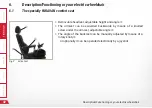
Description/Functioning or your electric wheelchair

45 

6.6 

Safe for traffic conditions according to German traffic law

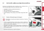
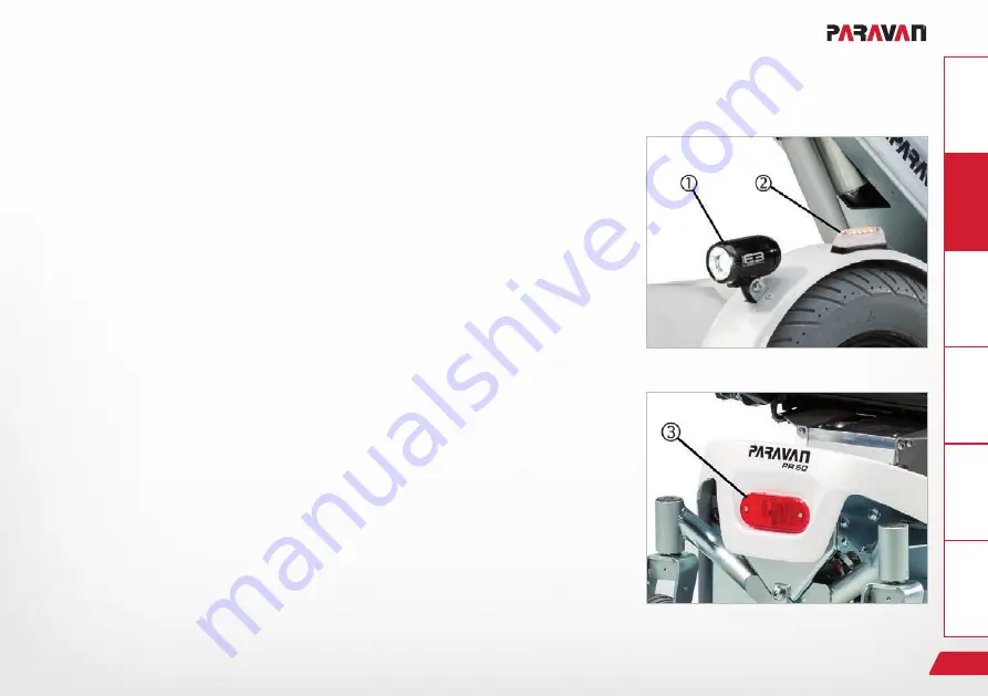
Fig. 10:   Front illumination

Fig. 11:   Rear illumination

Optionally, the PARAVAN electric wheelchair can be enhanced to be-

come a vehicle approved for use in road traffic using:


>

headlights for the best possible illumination 

.


>

directional indicators 

.


>

rear lights for the best possible visibility 

.


>

Lateral markings in the centres of the wheels using yellow reflec

-

tors.

6.6.1 

Section 24 Special means of transport


L

Wheelchairs are mentioned in German traffic law. In that law, 

it is stated:


>

(1) Push and grip wheelchairs, sleds, prams, scooters, children's bi

-

cycles and other similar means of transport are not vehicles in the 

sense of German traffic regulations.


>

(2) Medical wheelchairs and other wheelchairs as mentioned inPa

-

ragraph 1 may circulate wherever pedestrian traffic is permitted, but 

only at walking speed. 

Summary of Contents for PR 30

Page 1: ...User manual PR 30 PARAVAN WHEELCHAIR SERIES EN V3 1...

Page 2: ...Valid for the following model Paravan PR 30 Publisher and Copyright PARAVAN GmbH Date of issue 01 09 2020 Document number PR30_V3 1 EN...

Page 3: ...ation on the pages to follow in order to make sure your electric wheel chair will give you many years of problem free service Keep this User s Manual in a handy place for later reference Our user manu...

Page 4: ...ices 24 3 Safety note 25 3 1 General safety notes 25 3 1 1 Notes on usage 25 3 1 2 Notes on usage 29 3 1 3 Notes on transport 30 4 Functional description 31 4 1 Manufacturing standard 31 4 2 Appropria...

Page 5: ...ble 41 6 Description Functioning or your electric wheelchair 42 6 1 The specially PARAVAN comfort seat 42 6 2 Joystick control 43 6 3 Special controls 43 6 4 Lift and tilt seat inclination 44 6 5 Vibr...

Page 6: ...10 4 2 Setting the tibialis angle 55 10 4 3 Setting the foot rest angle 56 11 Use of the PARAVAN comfort seat 57 11 1 Setting the back support 57 11 1 1 Setting the back support angle 57 11 1 2 Setti...

Page 7: ...rough water 74 13 11 2 Climbing and overtaking capacity 75 13 11 3 Load bearing capacity 75 13 11 4 Impassible surfaces or areas 75 13 11 5 Slippery surfaces traction 75 14 Parking and storing your el...

Page 8: ...102 16 1 8 Select drive program drive 103 16 1 9 Electrical seat adjustment 104 16 1 10 Set time date 105 16 1 11 Show hide clock configure 12h 24h display 106 16 1 12 Adjust display brightness 107 16...

Page 9: ...2 15 Release the controls with the wheelchair switched off 120 Help 17 Getting out of your electric wheelchair 121 17 1 Procedure when getting out from the side 122 18 Care and maintenance 123 18 1 Se...

Page 10: ...ee accumulators 137 21 8 Notes on accumulators 138 21 9 Changing your accumulators 139 21 10 Charging your electric wheelchair 140 21 10 1 Procedure for charging your electric wheelchair 141 21 10 2 T...

Page 11: ...45 Fig 11 Rear illumination 45 Fig 12 Overview of wheelchair 46 Fig 13 Components rear of chassis 47 Fig 14 Components front of chassis 48 Fig 15 Armrest A8 52 Fig 16 Swivel mechanism 53 Fig 17 Lower...

Page 12: ...restraint with 4 point strap system 81 Fig 41 Positioning the occupant restraint for use with dahl docking system only 82 Fig 42 Dahl docking system 83 Fig 43 Content of Dahl Docking Station MK II st...

Page 13: ...ng function blocked 102 Fig 69 Select drive program 103 Fig 70 Joystick travelling direction 103 Fig 71 Display of seat functions 104 Fig 72 Set time function menu 105 Fig 73 Setting the time and date...

Page 14: ...isible 118 Fig 98 Setting the display brightness 119 Fig 99 Setting the display background 119 Fig 100 Blocking the controls 120 Fig 101 Controls blocked block symbol 120 Fig 102 Move foot rests 122 F...

Page 15: ...n Paravanstra e 5 10 D 72539 Pfronstetten Aichelau Tel 0 73 88 99 95 91 Fax 0 73 88 99 95 999 Email info paravan de Internet www paravan de Managing Director Mr Roland Arnold L Many smartphones and ta...

Page 16: ...exceptional cases within the limits set by the terms of the copyright law of the Federal Re public of Germany of 09 September 1965 in its version currently in force It will always be liable for paymen...

Page 17: ...ver its entire life cycle from transport delivery to decommissio ning taking out of service Below are listed and described the product s most important features All product features mentioned may be c...

Page 18: ...n PARAVAN GmbH does not take any responsibility for or give any guarantee against damages or operational interruptions that may be caused during operation by the non observance of the instructions con...

Page 19: ...e cover is defined exclusively by the relevant provisions set by PARAVAN Expressly excluded from guarantee entitlements is any damage resulting from Wear and tear Inappropriate operation or usage e g...

Page 20: ...utely prohibited All alterations must be executed by PARAVAN GmbH PARAVAN GmbH reserves the right to make technical alterations and improvements to the product in the interests of four customers and d...

Page 21: ...ivery Material damage to the electric wheelchair through non au thorised or incorrectly installed components Do not make any technical modifications to your electric wheelchair Only operate your elect...

Page 22: ...ectric wheelchair safely and how to move it about Knowledge of the safety and operational rules contained in it and of how to recognise possible hazards and dangerous situations for the user him or he...

Page 23: ...lways appears with an associated signal word which indicates the degree of danger Danger Imminent danger to life and limb irreversible Warning Possible danger to life and limb irreversible Caution Pos...

Page 24: ...hnology Safety note 24 2 3 1 Structure of safety notices You can find the following information in the safety notes Warning or hazard symbol Type and source of hazard Signal word Consequences of occur...

Page 25: ...Lifting move ment of the lift arm and the horizontal movement of the seat Danger of fall through accidental movement of the electric wheelchair due to the brake being left off Danger of fall through a...

Page 26: ...sons when using the electric wheelchair on downhill slopes with the seat position in its for wardmost position Danger of tipping over for persons when using he electric wheelchair when driving over ob...

Page 27: ...ivery Material damage to the electric wheelchair through non au thorised or incorrectly installed components Do not make any technical changes to your electric wheelchair Only operate your electric wh...

Page 28: ...load bearing capacity Material damage to the electric wheelchair through mechani cal and physical forces due to travelling over impassible sur faces Avoid travelling on slick slippery or greasy surfac...

Page 29: ...an 41 C Material damage to the electric wheelchair through battery overload on downhill slopes Use your electric wheelchair exclusively for the purpose for which it was intended Overloading the electr...

Page 30: ...lippage Both the ramp and the electric wheelchair transporter must be positioned on even and firm surfaces The ramp or lift must be clean and dry The ramp must be wider than the electric wheelchair an...

Page 31: ...highest possible level of safety for its operator and his or her immediate environment Our products are tested for freedom from any flaws after their manufac ture However if any failure in functionin...

Page 32: ...or areas The interface in relation to operation by the user and the liability of the manu facturer of the electric wheelchair is the control panel including its joystick and any optional operational u...

Page 33: ...ociated accessories Usage in areas governed by German traffic law public roads and thoroughfares on condition that full and fully functioning lighting is installed See Section 13 Driving the electric...

Page 34: ...suffering mechanical damage of any type The maintenance free VRLA accumulators and the equally maintenance free lead gel accumulators are clas sified as leak proof non hazardous cargo for any form of...

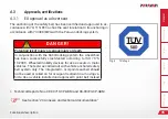
Page 35: ...P GBM and 08 00723 CP GBM See Section 23 Annexes and technical documentation Fig 4 T V Logo DANGER Potential risk of injury or serious injury or death In conjunction with the Dahl Docking system the w...

Page 36: ...ttemberg guidelines and standards and regulations and services page B 2 1 ff As auxiliary equipment permitted under the German regulations on assistive technology number HMV no 18 99 06 1048 4 3 3 Def...

Page 37: ...g training must be carried out as a therapeutic action and other standing aids e g underarm crutches axillary crutches walking frames cannot be used These wheelchairs are only used if manually operate...

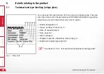
Page 38: ...read this information from the device s ratings plate They are very important in all correspondence with PARAVAM GmbH in guarante eing that you receive the technically correct advice Model designatio...

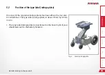
Page 39: ...label ratings plate has been affixed to your elec tric wheelchair The type label ratings plate is about 70mm by 40mm in size The type label ratings plate is positioned on the lower right of your whee...

Page 40: ...Please make sure that these details are listed when the wheelchair is handed over to you or if necessary enter the information yourself so that you have it to hand at all times Date of delivery hando...

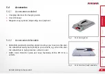
Page 41: ...c key optional depending on equipment 5 4 2 Accessories deliverable PARAVAN and DAHL docking station to allow you to secure the elec tric wheelchair easily and quickly in your vehicle e g when the ele...

Page 42: ...ir 6 1 The specially PARAVAN comfort seat Removable headrest adjustable height and angle j The armrest can be swivelled backwards by means of a knurled screw under the armrest adjustable angle k The a...

Page 43: ...ectric wheelchair s steering The electric wheelchair s braking behaviour Driving speed control of the two drive motors Secondary functions depending on the control panel and equipment being used 6 3 S...

Page 44: ...ay household and work environment At the press of a button you can adjust the seat tilt inclination as follows to the front which will give you assistance in standing up or to the rear for relaxing to...

Page 45: ...tion directional indicators rear lights for the best possible visibility Lateral markings in the centres of the wheels using yellow reflec tors 6 6 1 Section 24 Special means of transport L Wheelchair...

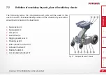
Page 46: ...lowing terms for components and parts will be used in this user s manual Their position on the wheelchair is shown in the illustration Control panel with joystick Repositionable armrest on multiple ax...

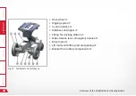
Page 47: ...The following terms for components and parts will be used in this user s manual Their assembled position on the chassis of your electric wheelchair is shown in the illustration Seat section Seat guid...

Page 48: ...electric wheelchair 48 Fig 14 Components front of chassis Drive wheel Rigging eyelet Control devices Stabilizer anti tipper Fitting for docking station Brake release lever emergency release Drive mot...

Page 49: ...sually that your electric wheelchair is in proper order Report any damage that may be due to trans port or delivery immediately in writing to your dealer forwarder or medical supplier and PARAVAN GmbH...

Page 50: ...ery complex and for your own safety can only be done by your service technician All parameters used in PARAVAN controls can be adjusted later to your needs and wishes These parameters include All driv...

Page 51: ...g elements are set to match your body mass However if any adjustment should be necessary then it can be made at any time Your PARAVAN electric wheelchair is build so that it can be adjusted to the nee...

Page 52: ...e Help Technology Settings on your electric wheelchair electronic 52 10 2 The armrest A8 This instruction applies both to the left and right hand side can be raised up max angel adjustable with the ad...

Page 53: ...0 3 Setting the movability of the control panel Fig 16 Swivel mechanism The horizontal swivel mechanism of the control panel can be set to ad just its level of stiffness i e in terms of the responsive...

Page 54: ...electric angle and length compensation enables the electrical ad justment of the length of the footrest unit and the adjustment of the angle to the seat The angle of the footrests can only be manuall...

Page 55: ...55 10 4 2 Setting the tibialis angle Fig 18 Tibialis angle The projection of the lower leg and of the tibialis angle between the up per and lower leg can be made using the angle setting of the PARAVA...

Page 56: ...nwards the foot rest is lowered Screw the adjustment screw outwards the foot rest is raised L Do not force the adjustment screw in or out Raise the foot rest a little to remove pressure on the adjustm...

Page 57: ...port angle The back support and the back support angle can be changed maually Turn the handwheel j on the side of the seat to adjust theback support angle The back support and the back support angle c...

Page 58: ...ings available Adjusting head inclination Push the head support into the required inclination push the head support up backwards or forwards Height adjustment in five stages Push the head support into...

Page 59: ...11 1 3 Setting your sitting position Fig 22 Sitting position The seat can be moved forward or backwards using the PARAVAN con trol if you have chosen this optional special accessory Select the menu i...

Page 60: ...provided within the control It must be set individually by the user Take the following steps in the following sequence when setting the ly ing position Select the menu in the control Move the lift arm...

Page 61: ...sing the PARAVAN control The stand up position function is not provided in the control It must be set individually by the user Take the following steps in the following sequence when setting the stand...

Page 62: ...cladding The chassis cladding can be removed for maintenance repair or cleaning Take the following steps in the following sequence when removing and reassembling the rear cladding Loosen and remove kn...

Page 63: ...d reattaching the side cladding Loosen and remove knurled screws Remove rear cladding See Section 12 1 Removing and reattaching the chassis clad ding Raise the side cladding at rear Disconnect the cab...

Page 64: ...y be legally required by the relevant legislati on to have an insurance policy for use of your electric wheelchair WARNING Danger of personal injury when operating the electric wheelchair in a state n...

Page 65: ...any trip L You may need to involve a second person for such a check Check that the brakes are working L The brake release lever must be positioned on LOCK i e in its upward position Charge state of yo...

Page 66: ...place of the buckle latch in the belt fastener when buckling the safety belt The function of the belt fastener is similar for all belt variants including 2 point belt lap belt 3 point belt in driver o...

Page 67: ...the following positions Joystick pushed forward the electric wheelchair travels forward Joystick to left or right the electric wheelchair changes its direc tion into the selected direction Joystick pu...

Page 68: ...ng on curves the rear of the vehicle swings outwards How to drive around a curve Press the joystick in the desired direction of movement forwards or backwards and at the same time Press the joystick i...

Page 69: ...he joystick the joystick will always return to its neutral position in the middle during travel the motor brake engages automatically and brakes the electric wheelchair Safety where power fails or cut...

Page 70: ...a stop depends very heavily on a number of factors such as Surface and nature of the surface being travelled on Total weight of the electric wheelchair vehicle plus driver L On braking during cruising...

Page 71: ...ectric wheelchair cannot be guaranteed during uphill or downhill travel involving a slope of more than 7 such travel will involve danger of the electric wheelchair tipping over When going downhill the...

Page 72: ...chair on the control panel You can reach the maximum final speed of the relevant drive level by pushing the joystick forward as far as it goes The functions of each of the drive levels are as follows...

Page 73: ...ve both brake release levers on the left and right hand side to UNLOCK their downward position L Do not switch to UNLOCK on sloping surfaces In this setting the drive motor has no braking function Set...

Page 74: ...he seat position in the most forward position Danger of tipping over for persons when using he electric wheelchair when driving over obstacles Avoid paths with any inclination of more than 10 When tra...

Page 75: ...h there is a danger that you may break through them and thus be come immobilised or overturn Always consider the total weight of the vehicle See Section 22 1 Technical information and dimensions 13 11...

Page 76: ...period of time Connect it up with the recharger Select a dry parking position Do not expose your electric wheelchair to high or low temperatures Cover your electric wheelchair with a suitable coverin...

Page 77: ...ted on the ramp must be greater than the height to be climbed from the floor to the height of the supporting edge in a car for example the floor of the car boot Check the load capacity of the ramp s o...

Page 78: ...The elec tric wheelchair must be secured in accordance with the DIN 75078 Parts 1 and 2 standard for powered vehicles in order for it to be conducted by persons with restricted mobility The electric w...

Page 79: ...or 4 point belts should not be re lied on for occupant restraint in a moving vehicle An approved vehicle anchored safety belt system should be used to secure occupant instead DANGER Belt must not be...

Page 80: ...recommended to use with 4 point strap restraint system rated for the total weight of the wheelchair in cluding any option 2 at front and 2 at the back that conforms to ISO 10542 1 If using a standard...

Page 81: ...not be held away from the body by wheelchair components such as armrest or wheels Restraints should be mounted to appropriate vehicle pillar and should not be held away from the body by wheelchair co...

Page 82: ...utton will not be contacted by wheelchair components during a crash WARNING Positioning the occupant restraint for use with Dahl docking system only When using wheelchair with Dahl docking system the...

Page 83: ...Docking Station MK II and VarioDock on the wheelchair using the PARAVAN adaption kit Please also refer to Dahl Engineerings instructions for ve hicle installation use and maintenance L The operation...

Page 84: ...wheelchair 84 WARNING Risk of injury through incorrect handling of the batteries Damage to property through incorrect handling of the batter ies Handle with special care May only be connected and disc...

Page 85: ...al Information Prepare Operate Help Technology Loading and transporting your electric wheelchair 85 Fig 43 Content of Dahl Docking Station MK II standard set 501750 15 6 1 Content of Dahl docking stat...

Page 86: ...General Information Prepare Operate Help Technology Loading and transporting your electric wheelchair 86 Fig 44 Content of Dahl VarioDock standard set 503600...

Page 87: ...0131 Locking rail for Dahl System PV Art Nr 000033184 Oval head screw ISO 7380 M8 x 12 Socket cap screw DIN 912 M12 X 20 Countersunk screw TORX ISO 14581 M8 x 35 14 9 Hexagon nut ISO 4032 M8 To instal...

Page 88: ...elchair 88 To remove the cover loosen all four knurled screws Remove the rear panel first then the side panels Disconnect the main cable plug from the batteries left and right Fig 47 Main Cable batter...

Page 89: ...hen remove the left and right batteries Position the Dahl system on the wheelchair chassis Fasten the Dahl system on both sides with four M8 x 12 pan head screws each Screw them in medium tight with a...

Page 90: ...ion of the counterpart in the vehicle Installation of the Dahl Docking systems in the vehicle Only professional companies in the business of converting or building wheelchair accessible vehicles can o...

Page 91: ...the PR 30 use the screws provided DANGER Potential risk of injury or serious injury or death due to use of incorrect screws Use the screws provided Do not use any other screws than those supplied fro...

Page 92: ...ion Lock plate and spacer Lock pin Red LED Green LED Control panel Release button Manual emergency release lever Manual operating lever Please refer to Dahl Engineerings installation and user guide fo...

Page 93: ...k plate is correctly se cured in the docking station As soon as the lock plate comes into contact with the locking pin a warning tone will sound a high pitched howl and the red diode lamp LED in the c...

Page 94: ...cking station If the wheelchair and user are not correctly secured If the warning tone sounds and or the red warning lamp LED in the control panel flashes or is lit Always check if the lock plate is p...

Page 95: ...ked activated again Move the wheelchair away from the docking station within this 5 or 8 second period Do not attempt to reverse out of the docking station until the red LED on the control module whic...

Page 96: ...scribed manual release procedures fails an emergency release tool made from red plastic comes with each docking station Move wheelchair forward to remove the pressure on the lock pin Place the emergen...

Page 97: ...ipped with displacement motors such as the lifting arm and the sitting functions must also be operated via the control panel On off key Selection of profile movement levels mode seat functions Directi...

Page 98: ...lds on the display Symbols of the status indicator Charging status of the storage batteries Direction indicator left On off light System status tortoise speed control active Direction indicator right...

Page 99: ...on off switch upwards The status display briefly flashes and the last selected function in terms of movement level seat function is shown Press the switch downwards again to Select movement levels 1...

Page 100: ...hes itself on and the light symbol lights up blue Press once more Light off j 16 1 5 Switch direction indicator on and off Press key or for the respective direction indicator left or right The selecte...

Page 101: ...azard lights key for the hazard lights on function The hazard lights switch themselves on while the hazard lights symbol flashes red and both direction of travel symbols flash green Press the key agai...

Page 102: ...ower drive program 1 to 5 Key to change speed in the drive program Drilling down the respective drive program Display of the current speed km h Trip display in kilometres Display turns black when a ch...

Page 103: ...ed into 5 levels once you drill down Press the switch upwards or downwards to switch to a higher or lower sub level The selected drive program and sub level will appear on the display Push the joystic...

Page 104: ...joystick left right The adjustment functions menu will appear on the display L Only the released or available functions can be selected To make the desired setting adjust the seat seat position liftin...

Page 105: ...r on the display Move the joystick left right to access the options year month date day of the week hours and minutes Select the desired option by mo ving the joystick left right Move the joystick up...

Page 106: ...r on the display Move the joystick left right to access the options year month date day of the week hours and minutes Select the desired option by moving the joystick Left Right The precise adjustment...

Page 107: ...software version Select the program function Press and hold the hazard lights key Select Auto Backlight from the settings Select On Off by moving the joystick left right To save quit the menu 16 1 13...

Page 108: ...until you hear a beeping sound Move the joystick forwards until you hear a beeping sound Move the joystick backwards until you hear a beeping sound Immobiliser is activated Switch on and a padlock sy...

Page 109: ...displacement motors such as the lifting arm and the sitting functions must also be operated via the control panel On off key Direction indicator right left keys Display showing the signal currently a...

Page 110: ...ons displayed in the assigned fields on the display Symbols of the status indicator Charging status of the storage batteries Direction indicator left On light System status tortoise Speed control Dire...

Page 111: ...switch off Fig 83 On off key Start Push the on off switch The last selected function in terms of movement level seat function is shown Switch off Push the on off switch The power wheelchair switches i...

Page 112: ...itches itself on and the light symbol lights up blue Press once more light off Fig 85 Light on and off Fig 86 Turn signal right left 16 2 5 Switch direction indicator on and off Press key or for the r...

Page 113: ...hazard lights key for the hazard lights on function The hazard lights switch themselves on while the hazard lights symbol flashes red and both direction of travel symbols flash yellow Press the key ag...

Page 114: ...a higher or lower drive program Key to change speed in the drive program Display showing trip in kilometres and current speed km h Display is blank when a charging device is connected If the wheelchai...

Page 115: ...ected drive profile will appear on the display Press the relevant key to select a higher or lower maximum end speed in the respective drive profile The preference within the drive profile will appear...

Page 116: ...The respective seat function will appear on the display L Only the functions present from the factory can be selected The required setting is carried out adjust the seat seat position lift backrest t...

Page 117: ...ill appear on the display Move the joystick right to access the options year month date day of the week hours and minutes Move the joystick Left Right to select the desired option The precise adjustme...

Page 118: ...de clock configure 12h 24h display Fig 97 Set clock to visible invisible Select the program function Press and hold the keys The Settings menu appears Use the joystick to select Display time By moving...

Page 119: ...e slower and faster speed keys Move the joystick Left Right to select the desired option To save quit the menu 16 2 13 Adjust display brightness Select the program function Press and hold the slower a...

Page 120: ...hear a beeping sound Move the joystick forwards until you hear a beeping sound Move the joystick backwards until you hear a beeping sound Immobiliser is activated Switch on and a padlock symbol appea...

Page 121: ...should have practised the manoeuvre often enough in the presence of another person You should consider what could happen if you were to fall to the floor without anyone being there to help you L We re...

Page 122: ...when getting out from the side During any move from the side follow this sequence of actions Position the electric wheelchair side on Set the required seat height Switch the electric wheelchair off Fo...

Page 123: ...ing little maintenance However the following considerations should be kept in mind to ensure problem free functioning It should be handled with care It should be kept clean It should be serviced annua...

Page 124: ...to clean the electric wheelchair Be careful that no elect ronics come in contact with water Only the following should be used for cleaning the frame and plastic components or painted layer Mild soaps...

Page 125: ...mentally friendly disposal L National and regional regulations on the disposal of waste should be followed For the purposes of recycling the electric wheelchair can be dismantled into following princi...

Page 126: ...ing is largely made of recyclable and environmentally harm less materials such as Wood e g pallets and outer packaging Metal e g tensioning straps Bubble wrap L Take advantage of the opportunity to re...

Page 127: ...following steps should be taken before putting it back into use Check all safety devices and repair them where necessary Undertake a complete service and revision Clean thoroughly L The electric wheel...

Page 128: ...s 128 19 3 Notes on transfer Where the PARAVAN electric wheelchair is transferred to new user all technical documentation required for safe use and operation such as The User s Manual and Service logs...

Page 129: ...tick button with your hand Low Battery This message appears when the control system detects that the battery voltage has dropped below 16 V Check the state of the batteries and the connections in the...

Page 130: ...in the control system Gone to sleep This message appears when the control system has been inactive for longer than the time period defined by the SleepTimer parameter Gyro disconnected This message ap...

Page 131: ...tire electrical system from any overload of electrical devices by activating immediately to cut off electricity from your electric wheelchair See Section 21 2 Main safety switch Secondary safety switc...

Page 132: ...voted green flag indicates that the main safety switch has been activated triggered 21 2 1 Resetting the main safety switch Push the flag indicating that the mains switch has been activated back into...

Page 133: ...on the left under the electric wheelchair s cladding L A raised button indicates that the secondary safety switch has activated 21 3 1 Resetting the secondary safety switch Remove cladding See Section...

Page 134: ...ownhill stretch the safety system switches to emergency stop in order to prevent damage to the electrical system control electronics etc L If the overload protection feature is activated triggered the...

Page 135: ...a variety of ancillary devices with a voltage of 12 or 24 volts to the electric wheelchair s own on board network If you have a need for this facility for example for a breathing apparatus please con...

Page 136: ...cement or maintenance tasks are practically no longer necessary If your electric wheelchair was delivered to you without a lighting system you can retrofit the system at any time Take the following st...

Page 137: ...osed The system is not designed to need or allow any refilling or topping up the electrolyte battery acid The state of charge or capacity of the accumulators can be seen from the control panel Red zon...

Page 138: ...charger when the electric wheelchair is not in use The recharger supplied switches automatically to maintain charge thus guaranteeing you that your accumulators in your electric wheelchair will always...

Page 139: ...tion or your electric wheelchair Move the lift arm upwards Remove cladding See Section 12 Removing and reattaching the chassis clad ding Disconnect power connection Disassemble the accumulators Remove...

Page 140: ...l capacity The best way to do this is to recharge nightly The charging time for your electric wheelchair should be 8 hours without any interruption The charging cycle is complete when the green lamp l...

Page 141: ...urface e g the foot supports Insert the charging device plug into the charging socket on the control panel Connect the charging device to the mains supply charging has started Check the charging statu...

Page 142: ...ns of 2006 95 EC Low Voltage Directive 2004 108 EC Electromagnetic Compatibility Directive L Read the Users Manual packed separately with the charging device 21 10 3 Positioning the charging device Us...

Page 143: ...as measured without seat 360mm 800mm Tilting Forward 21 Backward 50 Back angle Backward 67 Adjustment of foot position 120mm Seat length adjustment optional 180mm Foot angle adjustment optional 0 90...

Page 144: ...ength without foot rests reverse movement 900mm Total height standard seat including head support 1240mm Total height standard seat without head support 1050mm Electrics Accumulators 2 x 12 Volt Light...

Page 145: ...dard 6 km h optional max 10km h The maximum range was measured under test conditions Weight terrain and weather conditions may influence this figure in everyday operation When travelling on steeply in...

Page 146: ...our dealer or from PARAVAN GmbH See Section 1 1 Your manufacturer WARNING Danger of personal injury when operating the electric wheelchair in a state not conforming to its state upon delivery Material...

Page 147: ...erm excess oxygen from escaping before being fully recombined at the negative electrode Where charging is done improperly hydrogen will be emit ted as well as oxygen at the negative electrode This hyd...

Page 148: ...book 1 Inspection 12 months after commissioning Date Signature Stamp 2 Inspection annual Date Signature Stamp 3 Inspection annual Date Signature Stamp 4 Inspection annual Date Signature Stamp 5 Inspec...

Page 149: ...General Information Prepare Operate Help Technology Systems and technical documentation 149 23 3 EU Declaration of Conformity Fig 115 EU Declaration of Conformity...

Page 150: ...ack support Where using tilting always wear your safety belt Where using tilting travel only at half the speed of the selected driving level Seat and back support in the special orthopaedic seat Adjus...

Page 151: ...ot become caught up by the obstacle as this may cause the electric wheelchair to topple over Seat adjustment forward and back When you are moving the seat back or forwards make sure that the foot supp...

Page 152: ......

Page 153: ......

Page 154: ......

Page 155: ......

Page 156: ...stra e 5 10 72539 Pfronstetten Aichelau Germany Telephon 49 0 73 88 99 95 60 Fax 49 0 73 88 99 95 999 Email info paravan de www paravan com EN V3 1 User manual PR 30 PARAVAN WHEELCHAIR SERIES ORIGINAL...

Reviews: