Chapter 2 - Specification
Chapter 2 gives the specification of the T6M base station.
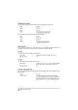
GENERAL
The general parameters of the T6M base station are listed below.
Operation
Simplex VHF AM transmit and receive.
Operating modes
Normal, priority, and scan.
Channel bandwidth
25 kHz and 8.33 kHz.
Frequency range (at 25 kHz)
Between 118 and 136.975 MHz.
Frequency range (at 8.33 kHz)
Between 118 and 136.9916 MHz.
Frequency stability
±
1.5 ppm
Channel selection
In Normal mode up to 760 channel frequencies can be
programmed into the radio. The channels can have
25 kHz spacing, 8.33 kHz spacing, or a mixture of both.
Priority mode allows up to 15 of the stored channels to
be allocated to a priority list. Channel selection can then
be limited to those frequencies in the priority list.
In Scan mode, the radio can have up to 15 scan groups
each containing up to 15 channel frequencies.
Duty cycle (receive)
Continuous.
Duty cycle (transmit)
25% with a maximum transmit time of 5 minutes. A
longer transmit time, or a higher duty cycle, reduces the
output power by up to 6 dB.
When the base station operates from the optional
internal battery, a duty cycle above 10% rapidly
discharges the battery (see ‘Optional Internal Battery’ on
page 14).
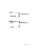
Operating temperature range
Between -20°C and +55°C.
Storage temperature range
Between -40°C and +70°C.
Humidity
Can be operated in humidity up to 80%.
Cooling
Fan assisted air flow. Fan turns on at approximately
40°C; the fan's speed increases as temperature
increases.
T6M Base Station User Guide
Page 13
Summary of Contents for T6M
Page 1: ...T6M Base Station User Guide Handbook Part Number 31 360T6MBS...
Page 12: ...Intentionally Blank T6M Base Station User Guide Page 12...
Page 16: ...Intentionally Blank T6M Base Station User Guide Page 16...
Page 48: ...Intentionally Blank T6M Base Station User Guide Page 48...
Page 56: ...Intentionally Blank T6M Base Station User Guide Page 56...
Page 58: ...Intentionally Blank T6M Base Station User Guide Page 58...
Page 59: ...BT6MBS 01 Front and Rear Layout Figure 1...
Page 60: ...BT6MBS 13 Rack Mounted Version Figure 2...
Page 62: ...BT6MBS 11 External Connection Diagram Figure 4...
Page 63: ...BT6MBS 10 Enclosure Securing Detail Figure 5...
Page 64: ...Base Station Block Diagram Figure 6 GA10547 Iss 3...
Page 65: ...Base Station Interconnection Diagram Figure 7 GA10548 Iss 3...
Page 66: ...Base Station Layout Diagram Figure 8 GA10719 Iss 1...
Page 69: ...Interface PCB Layout Diagram Figure 11 GA10751 Iss 1...
Page 70: ...BT6MBS 12 1 Cable Termination at the N Type Connector Figure 12...


