Transmit Inhibit
Any frequency programmed into the radio can be made ‘receive only’. To achieve this, the transmit
function on the channel is always inhibited, or the transmit facility can be inhibited only when the channel
is busy. If warning sounds have been set, a warning is heard when an attempt is made to key the
transmitter.
Maximum Transmit Time
A maximum continuous transmit time can be programmed into the radio's personality. The options are:
q
No limit.
q
A limit that can be set between 30 and 300 seconds.
q
If a limit has been set, and warning sounds have been set, the radio produces warning beeps
10 seconds before the transmission time expires.
FRONT PANEL DISPLAY FOR 25 kHz AND 8.33 kHz CHANNEL SPACING
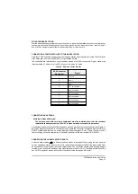
When selecting an 8.33 kHz channel frequency, the displayed frequency differs from the actual channel
frequency. Table 1 on page 27 shows the pattern used for 25 kHz and 8.33 kHz spaced channel
frequencies from 118.0000 MHz to 118.1916 MHz. The pattern is the same for any frequency within the
radio's frequency range. The display conforms to ICAO convention for 8.33 kHz operation.
Note that operation using 8.33 kHz channel spacing within the USA is not currently allowed under FCC
regulations.
T6M Base Station User Guide
Page 26
Summary of Contents for T6M
Page 1: ...T6M Base Station User Guide Handbook Part Number 31 360T6MBS...
Page 12: ...Intentionally Blank T6M Base Station User Guide Page 12...
Page 16: ...Intentionally Blank T6M Base Station User Guide Page 16...
Page 48: ...Intentionally Blank T6M Base Station User Guide Page 48...
Page 56: ...Intentionally Blank T6M Base Station User Guide Page 56...
Page 58: ...Intentionally Blank T6M Base Station User Guide Page 58...
Page 59: ...BT6MBS 01 Front and Rear Layout Figure 1...
Page 60: ...BT6MBS 13 Rack Mounted Version Figure 2...
Page 62: ...BT6MBS 11 External Connection Diagram Figure 4...
Page 63: ...BT6MBS 10 Enclosure Securing Detail Figure 5...
Page 64: ...Base Station Block Diagram Figure 6 GA10547 Iss 3...
Page 65: ...Base Station Interconnection Diagram Figure 7 GA10548 Iss 3...
Page 66: ...Base Station Layout Diagram Figure 8 GA10719 Iss 1...
Page 69: ...Interface PCB Layout Diagram Figure 11 GA10751 Iss 1...
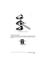
Page 70: ...BT6MBS 12 1 Cable Termination at the N Type Connector Figure 12...


