FAULT AND ERROR CODES
A number of fault and error codes are shown on the radio's display if an internal fault is detected. The
codes and their meaning are detailed in Table 2.
Table 2. Fault and Error Codes
Displayed
Fault or
Error Code
Title
Meaning
F1
Synthesiser
failure
An internal fault on the synthesiser has been detected. Switch off the base
station and switch on again after a few minutes. If the fault persists, refer to
‘Maintenance’ in chapter 7.
F2
Unstable
output
An internal fault on the power amplifier has been detected. Switch off the base
station and switch on again after a few minutes. If the fault persists, refer to
‘Maintenance’ in chapter 7.
F4
Over
temperature
This condition may occur if the transmitter's duty cycle has been exceeded, or
when transmitting for long periods. The fault should clear if the radio is not
keyed and allowed to cool.
F8
High reflected
power
Indicates a faulty antenna, antenna cable, or RF connector.
F16
F32
Low supply
voltage
High supply
voltage
These two faults indicate the internal power supply is faulty. Switch off the base
station and switch on again after a few minutes. If the fault persists, refer to
‘Maintenance’ in chapter 7.
Fault code F16 may be displayed when operating using the battery option and
the battery starts to run flat.
cErr
Critical error
This error is displayed when the base station is initially switched on and no
personality information, or corrupted personality information, is detected. Refer
to ‘Programming the Base Station’ on page 37 and load a personality into the
base station.
T6M Base Station User Guide
Page 28
Summary of Contents for T6M
Page 1: ...T6M Base Station User Guide Handbook Part Number 31 360T6MBS...
Page 12: ...Intentionally Blank T6M Base Station User Guide Page 12...
Page 16: ...Intentionally Blank T6M Base Station User Guide Page 16...
Page 48: ...Intentionally Blank T6M Base Station User Guide Page 48...
Page 56: ...Intentionally Blank T6M Base Station User Guide Page 56...
Page 58: ...Intentionally Blank T6M Base Station User Guide Page 58...
Page 59: ...BT6MBS 01 Front and Rear Layout Figure 1...
Page 60: ...BT6MBS 13 Rack Mounted Version Figure 2...
Page 62: ...BT6MBS 11 External Connection Diagram Figure 4...
Page 63: ...BT6MBS 10 Enclosure Securing Detail Figure 5...
Page 64: ...Base Station Block Diagram Figure 6 GA10547 Iss 3...
Page 65: ...Base Station Interconnection Diagram Figure 7 GA10548 Iss 3...
Page 66: ...Base Station Layout Diagram Figure 8 GA10719 Iss 1...
Page 69: ...Interface PCB Layout Diagram Figure 11 GA10751 Iss 1...
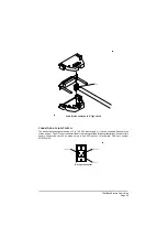
Page 70: ...BT6MBS 12 1 Cable Termination at the N Type Connector Figure 12...

