Chapter 3.
Controls, Indicators, and Connectors
This chapter details the purpose of all controls, indicators, and connectors
fitted to the transmitter's front and rear panels.
FRONT PANEL
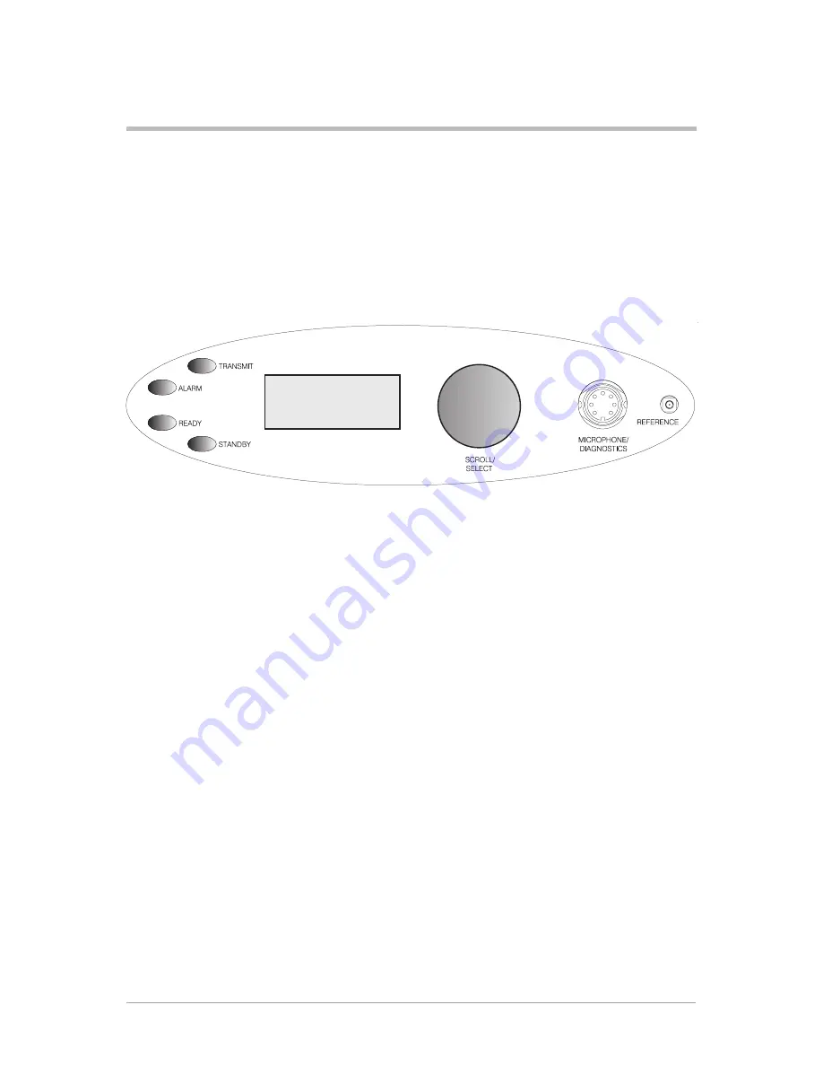
The front panel's controls, indicators, and connectors are shown below and described in the following
paragraphs.
Transmit Indicator
An amber indicator that lights when the transmitter is keyed and producing output power.
Alarm Indicator
A red indicator that either flashes, or lights, when a BIT fault has been detected. BIT indications are
classified as either warnings or faults.
If a warning is detected, the Alarm indicator flashes, the Ready indicator remains lit, and the transmitter
remains operational. A BIT warning is indicated if:
q
a high PA temperature is sensed
q
a high VSWR is sensed.
If a fault is detected, the Alarm indicator lights and the Ready indicator becomes unlit; the transmitter
cannot be used.
Ready Indicator
A green indicator that lights when the transmitter is ready for use and no BIT faults have been detected.
T6T General Information
Section 1
Page 11
F r e q
1 2 3 . 0 0 0 M H z
C h a n
1
O f f s e t
+ 5 . 0 k H z
P w r
l l l l l l l l l l l
Summary of Contents for T6T
Page 1: ...T6T Transmitter User Guide Issue 1...
Page 5: ...T6T Transmitter User Guide Section 1 General Information...
Page 12: ...Intentionally Blank Section 1 T6T Transmitter User Guide Page 8...
Page 24: ...Intentionally Blank Section 1 T6T Transmitter User Guide Page 20...
Page 32: ......
Page 33: ...T6T Transmitter User Guide Section 2 AM Voice Mode...
Page 40: ...Intentionally Blank Section 2 T6T AM Voice Operation Page 8...
Page 48: ...Intentionally Blank Section 2 T6T AM Voice Operation Page 16...


