background image

2

31

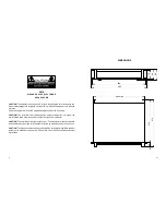
AVIS

RISQUE DE CHOC ELECTRIQUE

NE PAS OUVRIR

CAUTION!

 The amplifier runs on 230V AC voltage. Removing the cover will expose you

to a potentially dangerous voltage! Do not use the unit if the electrical power cord is frayed
or broken.
Power is supplied from 230V AC single-phase grounded 50/60 Hz source.

CAUTION!

  The  amplifier  can  yield  dangerous  output  voltage!  Do  not  touch  the

non-insulated cable parts connected to outputs of the unit in operation!

CAUTION!

 The amplifier yields high output power. The manufacturer shall not be held

responsible for any damage to the speakers caused by excessive power from the unit.

CAUTION!

 The high sound pressure caused by the high output signal applied to speaker

systems, may endanger your hearing. Please, take care to observe the required safety
precautions.

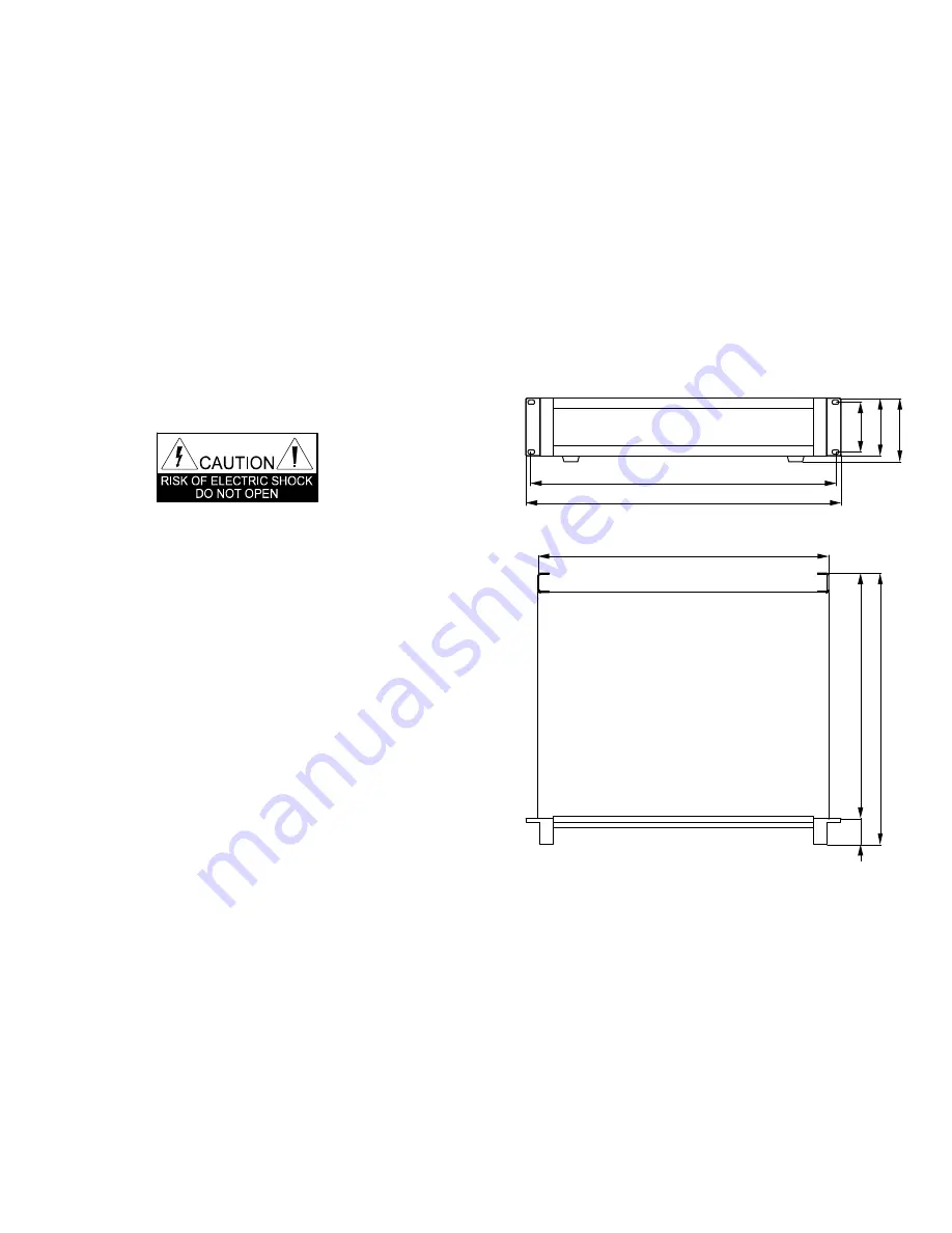
DIMENSIONS

445 max

4

0

3

7

4

4

1

4

482

466

7

6

8

8

9

6

Summary of Contents for V2-2400 MkIII

Page 1: ...IO II Ltd Vinnitsa Ukraine www parkaudio2 com e mail park parkaudio2 com PROFESSIONAL POWER AMPLIFIERS V series V4 900 V4 1200 V4 1800 V4 2400 V2 2400 MkIII MkIII MkIII MkIII MkIII OWNER S MANUAL PARK AUDIO II ...

Page 2: ...ACCESSORIES 1 Power Cord 1 ea 2 Owner s Manual 1 ea 3 Warranty 1 ea Printed in Ukraine ...

Page 3: ... Panel 11 Rear Panel 12 Input Module with Sensitivity Switch 13 Input Module with Crossover 14 Cabel Requirements 15 Input and Output Connectors 16 Rack Mounting Requirements 17 AC Power Requirements 17 Operating Modes 18 LinkingUp 21 Troubleshooting 27 Specifications 28 Operating Conditions 30 Dimensions 31 ...

Page 4: ...plifier can yield dangerous output voltage Do not touch the non insulated cable parts connected to outputs of the unit in operation CAUTION The amplifier yields high output power The manufacturer shall not be held responsible for any damage to the speakers caused by excessive power from the unit CAUTION Thehigh sound pressurecaused bythe high output signal applied to speaker systems may endanger y...

Page 5: ...ly in the schematics elements output power and weight Unless specified otherwise the word amplifier hereinafter applies to any of the above models UNPACKING The manufacturer s quality control system provides for careful examination of each product before it leaves the factory to ensure its flawless appearance After unpacking please check the unit for any physical damage In case of damage please co...

Page 6: ...ty even under overload In case of a short time overload lasting up to 3 msec e g overload caused by a sudden drop of total load impedance only the output stage current protection goes active limiting the current running through the output transistors at the safe level In this case the protection system does not preclude the amplifier from delivering for a short while a full output power without an...

Page 7: ...the output stage of the respective channel This status is indicated by a brightly full lit ALARM LED The amplifier automatically resumes its operation in the reverse order after the output stage transistors have cooled down Soft Start The soft start system is provided to reduce inrush current to the amplifier and to minimize the noise contributed by the amplifier to the power mains during the powe...

Page 8: ...s input module Input Filter only for input modules with a sensitivity switch or with a crossover To improve the performance of speaker systems the amplifier incorporates a switch selectable high pass 4 th order filter with a 24dB per octave slope rate This is the filter recommended by all major speaker systems manufacturers This filter cuts off any signals below 35Hz which generally cannot be repr...

Page 9: ... channels drive two separate loads from two separate signal sources MONO two channels drive two separate loads from a single input signal source BRIDGE two channels drive the same load from a single signal source The operating modes can be selected with the slide switch located on the rear panel Ground Lift This slide switch is used to decouple the signal ground and the chassis ground in order to ...

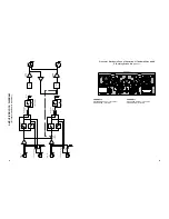
Page 10: ...2 Amplifier 1 CHANNEL2 SWITCHED OUTPUT HI position CROSSOVER LO position CHANNEL1 SWITCHED OUTPUT HI position CROSSOVER LO position AMPLIFIER BLOCK DIAGRAM Power amplifier Power amplifier Limiter Limiter CH 1 INPUT THROUGH MONO ST EREO BRIDGE MODE 1 1 2 2 OUTPUT OUTPUT CH 2 INPUT LEVEL LEVEL THROUGH ...

Page 11: ...Source To Channel 2 Input Signal Source Channel 2 Satellite Channel 1 Satellite Channel 2 Subwoofer Channel 1 Subwoofer AMPLIFIER BLOCK DIAGRAM for input modules with a sensitivity switch 775V 1 4V 32dB GAIN Power amplifier Power amplifier Limiter Limiter CH 1 INPUT THROUGH MONO ST EREO BRIDGE MODE LEVEL LEVEL ON OFF HI PASS FILTER 35Hz ON OFF HI PASS FILTER 35Hz 1 1 2 2 OUTPUT OUTPUT CH 2 INPUT T...

Page 12: ...ER HI position AMPLIFIER BLOCK DIAGRAM for input modules with crossover CROSSOVER CROSSOVER HF LF HF LF HI FULL RANGE LO CROSSOVER LEVEL LEVEL HI FULL RANGE LO CROSSOVER Power amplifier Power amplifier Limiter Limiter CH 1 INPUT SWITCHED OUTPUT LO THRU HI SWITCHED OUTPUT LO THRU HI MONO ST EREO BRIDGE MODE 125Hz 125Hz 125Hz 125Hz ON OFF HI PASS FILTER 35Hz ON OFF HI PASS FILTER 35Hz 1 1 2 2 OUTPUT...

Page 13: ...ite Channel 2 Subwoofer Channel 1 Subwoofer FRONT PANEL Power switch LEVEL input signal attenuators for channel 1 2 respectively ALARM LEDs Indicate alarm status and protection of the respective channel in case of DC output condition or powerful LF fluctuations output stage overheating Note See page 5 Thermal Protection CLIP overload LEDs Indicate overloading sound distortion and limiter activatio...

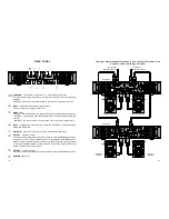
Page 14: ... two channels drive two separate loads from two separate input signal sources BRIDGE two channels drive a common load from a single input signal source INPUT balanced input XLR female for Channel 1 in STEREO Channels1 and 2 in MONO BRIDGE mode MAINS IN power cord socket for 230V AC 50 60Hz grounded mains OUTPUT Channel 1 output Is used to connect a load speaker system to Channel 1 with a SPEAKON c...

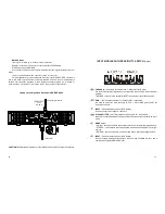
Page 15: ...on THROUGH line outputs for Channel 2 1 respectively XLR male Are used to deliver input signal along the respective channel to the input of another amplifier THROUGH connectors are parallel to INPUT connectors of respective channels GAIN input sensitivity switches for Channel 2 1 respectively Are used to select the input sensitivity 0 775V 1 4V or fixed gain 32 dB for respective channel INPUT Chan...

Page 16: ...nal delivered to the output of the respective channel CROSSOVER switch for channel 1 2 respectively Selects the desired frequency range to be amplified HI LO FULLRANGE The BRIDGE mode the frequency range is set by Channel 1 CROSSOVER switch INPUT MODULE WITH CROSSOVER Option Linking up the Signal and Speakers in MONO Mode CAUTION Never attempt to jumper or otherwise link up any pins of output conn...

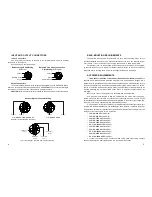
Page 17: ...r loss to the load at other cable lengths For example if you plan to deliver 500Watts to 8 Ohm load through 20m of 1 5 mm2 cable the power loss in the cable would be 2 9 x 2 5 8 of 500W or 29W lost in the cable Wire Gauge Cable Resistance Cable power loss 8Ohm load 1 5mm2 2 0mm2 2 5mm2 4 0mm2 0 24 Ohm 0 18 Ohm 0 15 Ohm 0 09 Ohm 10 7 8 3 7 4 3 2 9 2 2 1 8 1 1 2Ohm load 5 7 4 3 3 6 2 3 4Ohm load Pow...

Page 18: ...I V4 1800MkIII V4 2400MkIII V2 2400MkIII amplifiers are supplied with a three conductor grounded AC power cord and should be plugged into a standard 3 wire grounded electrical outlet which supplies 230VAC 50 60Hz Make sure to connect the amplifier only to sufficiently powerful power supply mains closer to a switch board If connected to weak power supply mains the output power of the amplifier may ...

Reviews: