background image

3

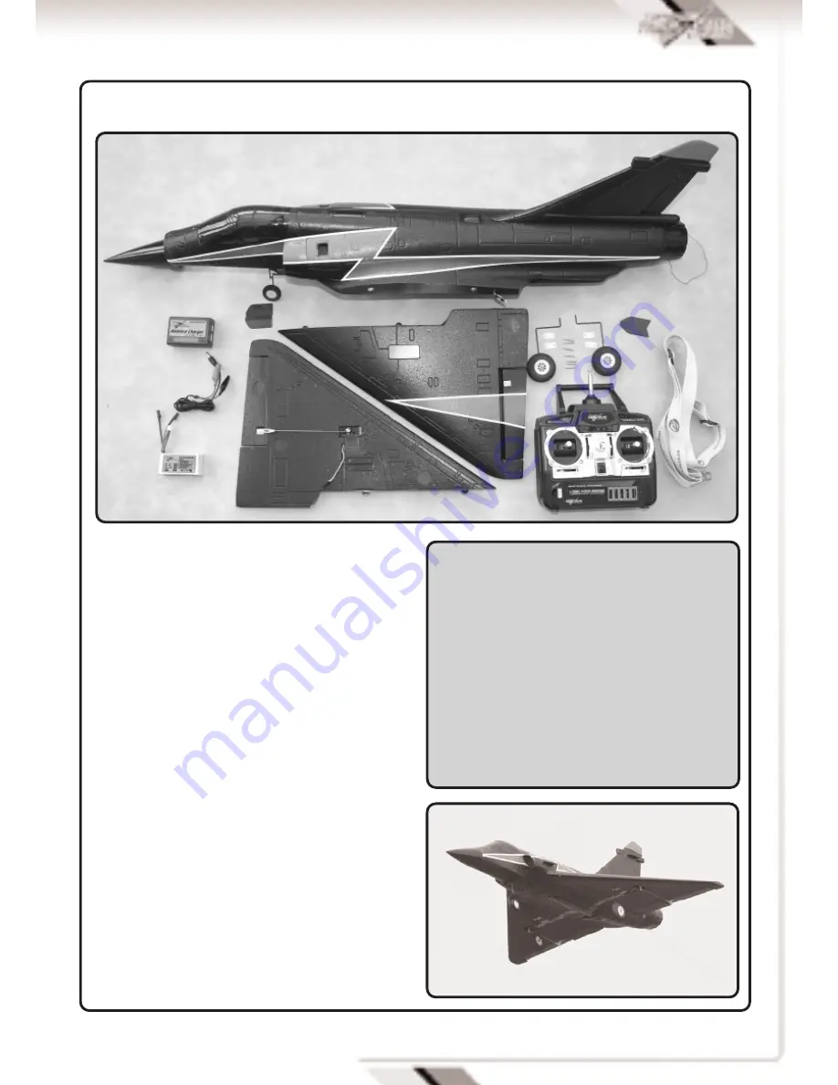
Fuselage with ducted fan, motor, Electronic
Speed Control (ESC) receiver, rudder- steering
servo, pushrods and nose wheel.

Two delta wing panels with ailerons connected to
factory installed servos 

Forward stabiliser canards (2 off)

Rear fin strake/ ECM Antennae

2 Main undercarriage assemblies with wheels
and mounting hardware 

4 function fully proportional 35Mhz transmitter

Adjustable quick release neck strap for
transmitter

Tube of adhesive

LiPo Battery 3 cell 11.1V 1300 mAh (15c)

2- 3 cell balance type 800mAh LiPo charger and
12v power lead

KIT CONTENTS AND DESCRIPTION

SPECIFICATIONS

Wing span:

680mm (26.75”)

Length:

980mm (38.5”)

Wing Area:

13 Dm

2

(200 sq inches)               

Weight:

565 g  (20 Ounces)

Radio:

4 function 35Mhz PPM
3 Qty micro servos   
25 Amp brushless ESC

Motor:

Brushless in runner 
5 blade ducted fan         
11.1v 1300mAh LiPo battery

Summary of Contents for Mirage 2000

Page 1: ......

Page 2: ...lying and we recommend that the model is flown at a recognised club with frequency control measures and suitable third party insurance The owner pilot of this model should take note of regulations and...

Page 3: ...ng hardware 4 function fully proportional 35Mhz transmitter Adjustable quick release neck strap for transmitter Tube of adhesive LiPo Battery 3 cell 11 1V 1300 mAh 15c 2 3 cell balance type 800mAh LiP...

Page 4: ...ockpit with profile pilot Nose cone supplied loose WING ASSEMBLY Supplied as two halves Each wing half includes undercarriage fixing plates and hinged aileron control surfaces Wing mounted aileron ser...

Page 5: ...er source a 12V car battery is ideal ensuring that correct polarity is observed Red is positive and Black is Negative Connect the lead into the matching socket of the battery charger and the Red LED w...

Page 6: ...ndicated by a bank of coloured LED s With green for full and red for empty As soon as the indicator changes to amber the model should be landed to allow battery replacement A red LED indicates dangero...

Page 7: ...the mating fuselage Press into position and use tape or bands to hold in place Wipe off any excess adhesive and allow to dry Repeat the procedure to the other wing Apply adhesive to the remaining wing...

Page 8: ...cut a narrow slot in the side of the fuselage behind the air intake A moulded in line gives the position Apply adhesive to the canard and insert into the slot Be sure to fit canard with its top face...

Page 9: ...rate in the correct manner and that surfaces for elevons Combined aileron and elevator are level Adjust surfaces if required by unclipping the pushrod clevis connectors and winding in or out to suit T...

Page 10: ...tor running If everything is okay take it to the flying field and rig it up again Always follow the frequency control procedures of your local flying site and ensure that you have adequate third party...

Page 11: ...to high speed aerobatic manoeuvers The control surface movements can be increased by moving the clevis connectors nearer to the control surfaces To reduce movements move the pushrod connections neare...

Page 12: ...EDF EP Ducted Fan w o Motor TGP0535 TGPF Outrunner Motor Mirage TGP0526 TGPF 1300mAh 12c 11 1v Lipo Battery Mirage TGE0001 Etronix 8 4G Micro Servo TGE0051 Etronix 25A Brushless Speed Control DISTRIBU...

Reviews: