background image

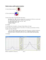
Aim Laser on End of Cantilever (Adjust Mirror 1)  


Open ‘XEP’ program, press OK if frequency sweep window opens. 
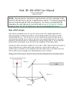
On the XE-100, the 

optical microscope position (‘Focus Stage’) is controlled through the software similarly to how 
the Z-stage position is controlled. When ‘Focus Follow’ is selected, the Focus Stage will match 
any movements made by the Z-stage – useful for keeping the cantilever in focus.


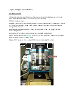
Find and focus on cantilever

:  If you don’t see the cantilever right away, first check that the 

Focus Stage

 is at the proper height to see the cantilever and check that enough light is coming 

from the light bank.  If you still don’t see the cantilever, you will need to adjust the position of 
the microscope (knobs located above head on microscope column).  Look at where the light from 
the microscope is shining on the tip assembly, as this will help you to center the microscope. 
 

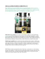
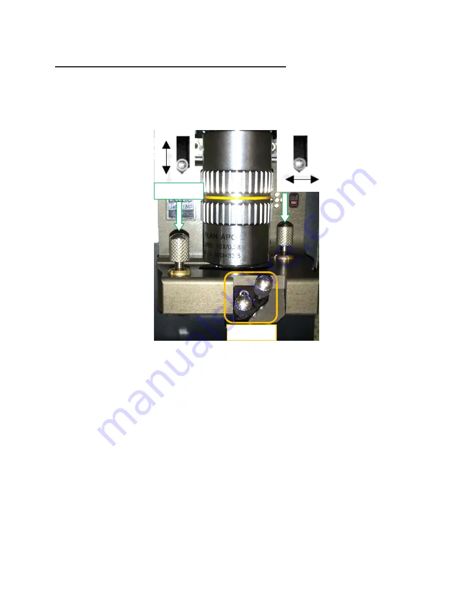
Position laser on cantilever: 

If you don’t see the laser reflected off the cantilever (and the laser 

is on), use the ‘Mirror 1’ knobs to move the laser along the vertical axis until you see it reflected 
on the edge of the probe, then move horizontally as needed.  Tightening the vertical position 
knob will raise the laser, loosening it will lower it. Aim the laser near the end of the cantilever 
(example above), where the deflection will be the greatest.   


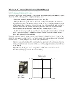
NOTE: Make sure that you position the 

primary

 beam spot - you may also see a 

reflected

 laser 

spot that will be dimmer.  To make sure you are aiming the primary beam spot on the end of the 
cantilever, move the laser to the base of the cantilever then loosen the vertical position knob.  
This will lower the laser position to the end of the cantilever. 

Mirror 2 

Mirror 1 

Summary of Contents for XE-100

Page 1: ...ser will move on the quadrant photodetector This is relayed to a motor controlling the tip which adjusts the tip s vertical position until the laser is aimed in the center of the quadrant photodetecto...

Page 2: ...ting tip and place it in the good tips box Ensure new tip is rested in place and that bearings fit into tip slots 4 Replace head and push flaps away from you until slightly tight This secures the head...

Page 3: ...n Look at where the light from the microscope is shining on the tip assembly as this will help you to center the microscope Position laser on cantilever If you don t see the laser reflected off the ca...

Page 4: ...e appropriate value If after several tries you still can t get the sum high enough remove the head and check mirror 2 s position visually it should be roughly parallel to the base Adjust mirror 2 knob...

Page 5: ...o 1 00 Cantilever General 4 Click OK 5 Turn Head back on in software Frequency Sweep Window will open 6 The software will automatically detect the cantilever s resonance peak and select a driving freq...

Page 6: ...B and C D are still less than 0 3 V 9 Shut acoustic enclosure 10 Click Approach button in Z stage control When the approach stops the light in the Z stage Control window will stop blinking Ensure tha...

Page 7: ...will change the distance the tip hovers above the sample surface when scanning and can improve resolution of features surface tracking This can be done manually by changing the number in the Set Poin...

Page 8: ...h XEI You can send images directly to the XEI data analysis software from the Buffer in XEP by right clicking on them Or you can open them from the spmdata or User Files folders Flattening your sample...

Page 9: ...er as needed 5 Turn off laser switch unplug head and remove head 5a If the tip you used was good leave it on the AFM Otherwise remove head and place tip in the Bad Probes box 6 Remove sample from stag...

Page 10: ...ion on center of photodetector A B 3 5V A B and C D 0 3V 6 Select appropriate mode scanner and frequency 7 Approach surface i Get optically close several mm ii Focus microscope 50 100um from surface m...

Reviews: