background image

   English

1 / 14

  ATT140-340 

1 Safety

1.1  Importance of the manual

•  Keep it for the entire life of the machine.
•  Read it before any operation.
•  It is subject to changes: for updated information see the version on 
the unit.

1.2 Warning signals

!

Instruction for avoiding danger to persons

Y

Instruction for avoiding damage to the equipment.

Z

The presence of a skilled or authorized technician is required.

,

There are symbols whose meaning is given in the para. 9.1

1.3 Safety instructions

Every unit is equipped with an electric disconnecting switch for 

operating in safe conditions. Always use this device in order to eliminate 
risks maintenance.

!

 The manual is intended for the end-user, only for operations per-

formable with closed panels: operations requiring opening with tools 
must be carried out by skilled and qualifi ed personnel.

Y

 Do not exceed the design limits given on the data plate.

!Y


It is the user’s responsibility to avoid loads different from the 

internal static pressure. The unit must be appropriately protected when-
ever risks of seismic phenomena exist.

The safety devices on the compressed air circuit must be provided 

for by the user
Only use the unit for professional work and for its intended purpose.
The user is responsible for analysing the application aspects for product 
installation, and following all the applicable industrial and safety stand-
ards and regulations contained in the product instruction manual or oth-
er documentation supplied with the unit.
Tampering or replacement of any parts by unauthorized personnel and/
or improper machine use exonerate the manufacturer from all responsi-
bility and invalidate the warranty. 
The manufacturer declines and present or future liability for damage to 
persons, things and the machine, due to negligence of the operators, 
non-compliance with all the instructions given in this manual, and non-
application of current regulations regarding safety of the system.
The manufacturer declines any liability for damage due to alterations 
and/or changes to the packing.
It is the responsibility of the user to ensure that the specifi cations  pro-
vided for the selection of the unit or components and/or options are fully 
comprehensive for the correct or foreseeable use of the machine itself 
or its components.

!

IMPORTANT: The manufacturer reserves the right to modify 

this manual at any time. The most comprehensive and updated 
information, the user is advised to consult the manual supplied 
with the unit.

1.4 Residual risks

The installation, start up, stopping and maintenance of the machine 
must be performed in accordance with the information and instructions 
given in the technical documentation supplied and always in such a way 
to avoid the creation of a hazardous situation. 
The risks that it has not been possible to eliminate in the design stage 
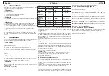
are listed in the following table:

Part affected

Residual

risk

Manner of

exposure

Precautions

heat exchanger 
coil

small cuts

contact

avoid contact, wear 
protective gloves

fan grille and 
fan

lesions

insertion of pointed 
objects through the 
grille while the fan is 
in operation

do not poke objects of 
any type through the 
fan grille or place any 
objects on the grille

inside the 
unit:
compressor 
and dis-
charge pipe

burns

contact

avoid contact, wear 
protective gloves

inside the 
unit: metal 
parts and 
electrical 
wires

intoxica-
tion, 
electrical 
shock, 
serious 
burns

defects in the 
insulation of the 
power supply lines 
upstream of the 
electrical panel; live 
metal parts

adequate electrical 
protection of the power 
supply line; ensure metal 
parts are properly con-
nected to earth

outside the 
unit: area 
surrounding 
the unit

intoxica-
tion, seri-
ous burns

fi re due to short 
circuit or overheating 
of the supply line up-
stream of the unit’s 
electrical panel

ensure conductor cross-
sectional areas and the 
supply line protection 
system conform to appli-
cable regulations

outside the 
unit:

lesions

loss of desiccant

clean the area around 
the unit

components 
subjected to 
compressed: 
air

lesions on 
rhe eyes, 
ears and 
body

defect assembly,  
breakage caused by 
pulse of air, espe-
cially at startup

Use the personal protec-
tive equipment: hearing 
protection, glasses, 
helmet, suit and shoes.

9 Appendix

9.1 Legend
9.2 Installation diagram
9.3 Technical data
9.4  Spare parts list
9.5 Exploded drawing
9.6 Dimensional drawings
9.7 Refrigerant circuit
9.8 Wiring diagram

Index

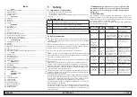
1 Safety 

1

1.1  Importance of the manual ................................................................1
1.2 Warning signals ................................................................................1
1.3 Safety instructions ............................................................................1
1.4 Residual risks ...................................................................................1

2 Introduction 

2

2.1 Transport 

...........................................................................................2

2.2 Handling ...........................................................................................2
2.3 Inspection .........................................................................................2
2.4 Storage .............................................................................................2

3 Installation 

2

3.1 Procedures .......................................................................................2
3.2 Operating space ...............................................................................2
3.3 Versions ............................................................................................2
3.4 Tips ...................................................................................................2
3.5 Electrical connection ........................................................................2
3.6  Condensate drain connection ..........................................................2
3.7  Connections discharge purge air ......................................................2
3.8  Connection to the air bleeder ...........................................................2
3.9  Connecting the fi lter oil drainage ......................................................2

4 Commissioning 

3

4.1 Preliminary checks ...........................................................................3
4.2 Starting .............................................................................................3
4.3 Operation ..........................................................................................3
4.4  Operation with Dew point control .....................................................3
4.5 Stop ..................................................................................................4
4.6 Language selection ..........................................................................4
4.7  Precautions during commissioning and operation ...........................4

5 Control 

4

5.1 Control panel ....................................................................................4
5.2 Operating states ...............................................................................4
5.3 Screens displayed ............................................................................5
5.4 Energy saving ...................................................................................6
5.5  Alarms and warnings ........................................................................6

6 Maintenance 

7

6.1 General instructions 

..........................................................................7

6.2 Refrigerant ........................................................................................7
6.3 Desiccant agent 

................................................................................7

6.4  Preventive Maintenance Programme ...............................................7
6.5 Dismantling .......................................................................................8

7 Alarm 

list 

9

8 Troubleshooting 

12

Summary of Contents for ATT140

Page 1: ...IT Manuale d uso EN User Manual ES Manual de uso DE Benutzer Handbuch ATT140 ATT260 ATT340 DATE 04 05 2017 Rev 21 CODE 398H272986 ATT Antares Tandem Dryer 50Hz...

Page 2: ......

Page 3: ...comunque in modo che non venga generata alcuna situazione di rischio I rischi che non stato possibile eliminare in fase di progettazione sono riportati nella tabella seguente Parte Considerata Rischi...

Page 4: ...dell ambiente circostante conten ga contaminanti solidi e o gassosi attenzione quindi a zolfo ammonia ca cloro e ad installazioni in ambiente marino Per le versioni con ventilatori assiali sconsigliat...

Page 5: ...verso da 40 C possibile lavorare in modalit Dew Point Control Il sistema automaticamente controller la durata dei cicli di funzionamento per raggiungere e mantenere il dew point desiderato risparmiand...

Page 6: ...VICE INFORMATION Selezionare Language e confermare con Enter User Settings Menu DRYER SETTINGS DATE TIME BMS MOISTURE DRAIN OTHER LANGUAGE Selezionare con UP e DOWN la lingua Confermare con Enter LANG...

Page 7: ...matico manuale Una volta modificato il parametro confermare con Enter Le altre maschere visualizzabili in questa sezione sono le seguenti Premere Esc per tornare a USER SETTINGS MENU Selezionare DATE...

Page 8: ...SAVING 000000009 Questa maschera accessibile dalla maschera principale premendo due volte il tasto DOWN dalla maschera principale Procedura per l abilitazione di tale maschera 1 Accedere in PRG USER...

Page 9: ...a Y L apparecchiatura contiene gas fluorurati a effetto serra Il fluido frigorigeno R407c a temperatura e pressione normale un gas incolore appartenente al SAFETY GROUP A1 EN378 fluido gruppo 2 second...

Page 10: ...ngresso aria n 22 Attenzione il dryer ancora in pressione nella zona di uscita aria cooler 3 depressurizzare l impianto utilizzando una valvola in uscita se presente o utilizzare lo scarico del filtro...

Page 11: ...re NU X A 3 s AIN sonda sullo scarico compressore non funzionate S N Attivo A07 WARNING PROBE Thermal MassTemperature NU X A 3 s AIN sonda temperatura massa termica non funionante N N Attivo A08 WARNI...

Page 12: ...alta pressione pressostato A N N Attivo A22 WARNING ADSORBER Low Pressure Column 2 X X X A 120s DIN bassa pressione pressostato B N N Attivo A23 WARNING ADSORBER High Pressure Column 2 X X X A 120s D...

Page 13: ...X A Errore sonda di pressione colonna 1 N N Attivo A37 WARNING PROBE PRESSU RE COLUMN 2 NU X X A Errore sonda di pressione colonna 2 N N Attivo A38 WARNING Pressure Discharge Failure Column 1 NU X X A...

Page 14: ...sore No Si Mancanza di refri gerante Si Pulire il condensatore Elevata perdita di carico Scambiatore intasato No Filtri intasati No Formazione ghiaccio No Si Pulire lo scambiatore e sostituire prefilt...

Page 15: ...ntilatore starato No Mancanza refrigerante ricaricare Z Si Sostituire pressosta to ventilatore Z No Carico termico eccessivo No Low AD inlet temperature Valvola gas caldo starata Si No Pressostato ven...

Page 16: ...Italiano 14 14 ATT140 340...

Page 17: ...med in accordance with the information and instructions given in the technical documentation supplied and always in such a way to avoid the creation of a hazardous situation The risks that it has not...

Page 18: ...void installations where the surrounding air contains solid and or gaseous pollutants e g sulphur ammonia chlorine and installations in marine environments The ducting of extracted air is not recommen...

Page 19: ...ifferent dew point of 40 C it is possible to work in Dew Point Control The system automatically controls the time of the cycles of operation to obtain and maintain the predetermined dew point with the...

Page 20: ...TTINGS SERVICE INFORMATION Select Language Press Enter to confirm User Settings Menu DRYER SETTINGS DATE TIME BMS MOISTURE DRAIN OTHER LANGUAGE Using UP and DOWN select the language Press Enter to con...

Page 21: ...point mode automatic manual When you change the parameter press Enter to confirm Press Esc to return on USER SETTINGS MENU Select DATE for change the date and the time User Settings Menu DRYER SETTIN...

Page 22: ...This Screen appears ENERGY SAVING 000000009 Steps to enable these functions 1 Press PRG than USER than SETTINGS than OTHER This Screen appears U12 BACKLIGHT ON NO U13 Enable Money NO U14 Money Euro U...

Page 23: ...any damage caused by incorrect refrigerant replacement carried out by unauthorized personnel will not be covered by the war ranty Y The equipment contains fluorinated greenhouse gases At normal temper...

Page 24: ...urize the dryer using a valve air out cooler if installed by the user or use the drain valve of the dust filter 29 4 Make sure that the pressure on gauge 0 bar AIR OUT n 36 37 The desiccant vessels ar...

Page 25: ...A 3 s AIN Compressor Discharge Temperature Y N Active A07 WARNING PROBE Thermal MassTemperature Nu X A 3 s AIN Thermal Mass Temperature PROBE Not Connected Or Faulty N N Active A08 WARNING PROBE Capa...

Page 26: ...22 WARNING ADSORBER Low Pressure Column 2 X X X A 120s DIN Air Pressure Switch B N N Active A23 WARNING ADSORBER High Pressure Column 2 X X X A 120s DIN Air Pressure Switch B N N Active A24 WARNING AD...

Page 27: ...X A Error pressure PROBE column 1 N N Active A37 WARNING PROBE PRES SURE COLUMN 2 NU X X A Error pressure PROBE column 2 N N Active A38 WARNING Pressure Dis charge Failure Column 1 NU X X A If at the...

Page 28: ...eteriorated No Yes low level refrigerant Yes Clean the condenser High pressure drop Exchanger dirty No Filters dirty No Formazione ghiaccio No Yes Clean the exchenger and substitute the pre filter Yes...

Page 29: ...switch PV not set No refrigerant recharge Z Yes Replace pressure switch Z Excessive thermal load Low AD inlet Tem peratur Hot gas valve not cali brated Yes Fan pressure switch PV not set Calibrate va...

Page 30: ...English 14 14 ATT140 340...

Page 31: ...ndo la generaci n de situaciones peligrosas En la siguiente tabla se recogen los riesgos que no se hayan podido eliminar en la fase de dise o Pieza afec tada Riesgo residual Forma de exposi ci n Preca...

Page 32: ...cloro e instalaciones en entornos marinos La ventilaci n del aire extra do no es recomendada para las versiones con ventiladores axiales 3 5 Conexi n el ctrica Use un cable aprobado de acuerdo con la...

Page 33: ...Punto de Roc o El sistema controla de forma autom tica la duraci n de los ciclos de funcionamiento para obtener y mantener el punto de roc o predeter minado ahorrando energ a en caso de trabajar con...

Page 34: ...ndo la m quina est apagada 4 6 Selecci n de idioma Seleccione USER SETTINGS Pulse Enter para confirmar Main Menu START STOP USER SETTINGS SERVICE INFORMATION Seleccione Language Pulse Enter para confi...

Page 35: ...las Up Down y Enter puede seleccionar cambiar un par metro U1 SET de Punto de Roc o U2 presi n de trabajo barg U3 Modo de Trabajo Forced Rig O Normal U4 Modo de Aviso de Alarma mediante alarmas y adve...

Page 36: ...OFF OPEN L SWITCH Closed CLOSE L SWITCH Open 5 4 Ahorro de energ a 5 4 1 AHORRO DE ENERG A kWh El usuario puede ver c mo la unidad ahorra kWh en comparaci n con un aparato similar de los siguientes ti...

Page 37: ...ga de refrigerante p ngase en contacto con personal cualificado y autorizado Y La v lvula Schrader s lo deber utilizarse en caso de que el apa rato no funcione de lo contrario cualquier da o causado p...

Page 38: ...marquen 0 bar entrada del aire n 22 Atenci n el secador todav a est bajo presi n en la zona de salida del aire del enfriador 3 Despresurizar el sistema utilizando una v lvula en salida si est present...

Page 39: ...Temperature Nu X A 3 s AIN Temperatura de descarga del compresor S N Activo A07 WARNING PROBE Thermal MassTemperature Nu X A 3 s AIN PROBE de la Temperatura de Masa t rmica No Co nectado o Defectuoso...

Page 40: ...N Interruptor de Presi n del Aire A N N Activo A22 WARNING ADSORBER Low Pressure Column 2 X X X A 120s DIN Interruptor de Presi n del Aire B N N Activo A23 WARNING ADSORBER High Pressure Column 2 X X...

Page 41: ...vo A37 WARNING PROBE PRESSU RE COLUMN 2 NU X X A Error PROBE de presi n columna 2 N N Activo A38 WARNING Pressure Dischar ge Failure Column 1 NU X X A Si al final de la fase de drenaje la presi n es 3...

Page 42: ...l com presor deteriorados No S Nivel bajo refrigerante S Limpie el conden sador Ca da de la alta presi n Intercambiador sucio No Filtros sucios No Formaci n de hielo No S Limpie el inter cambiador y c...

Page 43: ...rigerante recarga Z S Cambie el interruptor de la presi n Z Carga t rmica excesiva Temperatura de entrada AD baja V lvula de gas caliente sin calibrar S Interruptor de presi n del ventilador PV sin co...

Page 44: ...Espa ol 14 14 ATT140 340...

Page 45: ...in den technischen Ger teunterlagen strikt einzuhalten in jedem Fall ist jedes Vorgehen zu vermeiden dass zu ei ner Gefahrensituation f hrt Die Restrisiken die beim Bau der Maschine nicht beseitigt w...

Page 46: ...rs sollte von einer Installation in Bereichenabgesehenwerden indenendieLuftfesteund odergasf rmige kontaminierende Stoffe enth lt z B Schwefel Ammoniak Chlor das gilt auch f r Installationen in Meeres...

Page 47: ...verschiedener Taupunkt gew nscht wird kann die Betriebsart Taupunktregelung gew hlt werden Das System berwacht automatisch die Dauer der Arbeitszyklen um den gew nschten Tau punkt zu erreichen oder a...

Page 48: ...status OFF Keine Luft in die Tanks mit dem Trock nungsmittel einstr men lassen wenn die Maschine ausgeschaltet ist 4 6 Sprache anw hlen USER SETTINGS anw hlen und mit Enter best tigen Main Menu START...

Page 49: ...r zu ndernde Parameter ausgew hlt U1 EINSTELLWERT Taupunkt U2 Arbeitsdruck barg U3 Betriebsart Zwangreg O Normal U4 Alarm Relay Mode by alarms warnings oder nur Fehlermeldungen U6 DPM Fitted oder No F...

Page 50: ...ige der Energieersparnis 5 4 1 ANZEIGE DER ENERGIEEINSPARUNG IN kWh Es ist m glich die Energieeinsparung der Maschine in kWh im Vergleich zu einem der folgenden analogen Ger te anzuzeigen Kalt regener...

Page 51: ...Das Schrader Ventil darf nur im Falle einer ungew hnlichen Be triebsst rung verwendet werden anderenfalls bestehen bei einer fal schen K ltemittelbef llung keine Garantieanspr che 6 2 K ltemittel Y B...

Page 52: ...ass Nr 22 ob der Druck 0 bar betr gt Achtung Der Trockner steht im Luftauslassbereich des K hlers noch unter Druck 3 Setzen Sie das System mit Hilfe des Luftauslassventils sofern vorhanden oder des Ab...

Page 53: ...sor DischargeTemperature Nu X A 3 s AIN F hler am Kompressorauslass defekt J N Aktiv A07 WARNING PROBE Thermal MassTemperature Nu X A 3 s AIN Temperaturf hler thermische Masse defekt N N Aktiv A08 WAR...

Page 54: ...DIN Hochdruck Druckschalter A N N Aktiv A22 WARNING ADSORBER Low Pres sure Column 2 X X X A 120s DIN Niederdruck Druckschalter B N N Aktiv A23 WARNING ADSORBER High Pres sure Column 2 X X X A 120s DIN...

Page 55: ...6 WARNING PROBE PRESSU RE COLUMN 1 NU X X A Fehler Druckf hler S ule 1 N N Aktiv A37 WARNING PROBE PRESSU RE COLUMN 2 NU X X A Fehler Druckf hler S ule 2 N N Aktiv A38 WARNING Pressure Dischar ge Fail...

Page 56: ...digt Nein Ja K ltemittel unzureichend Ja Den Kondensator rei nigen Hohe Druckverluste W rmetauscher verstopft Nein Filter verstopft Nein Eisbildung Nein Ja W rmetauscher reinigen und Vorfilter ersetz...

Page 57: ...f llen Z Ja Druckw chter ersetzen Z W rmelast zu hoch Niedriger AD Eintritt temperatur Hei gas Ventil unkorrekt eingestellt Ja Druckw chter Ven tilator PV unkorrekt eingestellt Ventil einstellen Z Nie...

Page 58: ...Deutsch 14 14 ATT140 340...

Page 59: ......

Page 60: ...co MI Italy Sede Operativa Gas Separation and Filtration Division EMEA Strada Zona Industriale 4 35020 S Angelo di Piove PD Italy tel 39 049 971 2111 fax 39 049 9701911 Web site www parker com hzd e m...

Reviews: