background image

   Deutsch

  ICE003-005 

5 / 6

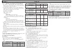
4.6  Verwaltung der Alarme

4.6.1 

Alarme   

CODE

Beschreibung

Rückstellung.

E0

Fehler des Sensors für Regelung

M

EE

Fehler in Datenerfassung

M

4.7 Automatischer Neustart

Bei einem Ausfall der elektrischen Versorgung bleibt nach deren Wie-
derherstellung der Status des Kaltwassersatzes ON bzw. OFF unverän-
dert.

5 Wartung

a) Die Einheit ist entsprechend ausgelegt, um kontinuierlichen Dau-

erbetrieb zu gewährleisten; die Betriebslebensdauer der jeweiligen 
Komponenten ist jedoch direkt von der ausgeführten Wartung 
abhängig.  

b) Für die Anforderung von Serviceeingriff en oder Ersatzteilen sind 

die Angaben auf dem Typenschild an der Außenseite der Einheit zu 
notieren (Modell und Seriennummer) und dem Wartungsservice 
mitzuteilen.  

c) Die Kältekreise, die eine Kältemittelmenge von 3 kg oder darüber 

enthalten, sind mindestens einmal jährlich auf eventuelle Leckstellen 
zu überprüfen.
Die Kältekreise, die eine Kältemittelmenge von 30 kg oder darüber 
enthalten, sind mindestens einmal in sechs Monaten auf eventuelle 
Leckstellen zu überprüfen (EG 842/2006, Art. 3.2.a, 3.2.b).

d) Für Maschinen, die eine Kältemittelmenge von 3 kg oder darüber 

enthalten, muss der Techniker ein Register führen, in das die Menge 
und der Typ des verwendeten Kältemittels sowie die eventuell 
zusätzlich eingefüllten und während der Wartung, Reparatur sowie 
endgültigen Entsorgung aufgefangenen Mengen eingetragen werden 
(EG 842/2006, Art. 3.6). Ein Beispiel eines solchen Registers kann 
auf folgender Website heruntergeladen werden: www.polewr.com.

5.1 Allgemeine Hinweise

Vor jedem Wartungseingriff  muss kontrolliert werden, dass das 

Gerät nicht mehr gespeist wird.

Y

 Stets Original-Ersatzteile des Herstellers verwenden; anderenfalls 

übernimmt der Hersteller keinerlei Haft ung bei Fehlbetrieben der 
Einheit.

Y

 Bei Verlust von Kältemittel ist erfahrenes und autorisiertes Fach-

personal zu kontaktieren.

Y

 Das Schrader-Ventil ist nur im Fall eines von der Norm abwei-

chenden Betriebs der Einheit einzusetzen; anderenfalls werden Schä-

den infolge unkorrekter Kältemittelbefüllung nicht von der Garantie 
abgedeckt.

5.2 Vorbeugende Wartung

Für eine stets optimale Effi

  zienz und Zuverlässigkeit des Chiller wer-

den empfohlen:

a) 

alle 4 Monate -

 Reinigung der Rippen des Kondensators und 

Überprüfung der Stromaufnahme des Verdichters, die innerhalb der 
Typenschildwerte liegen muss;

b) 

alle 3 Jahre -

 Installation des Sets für Wartung alle 3 Jahre

Folgendes ist lieferbar (siehe Abschnitt 7.3):

a) 

Set für Wartung alle 3 Jahre;

b)

Service-Set;;

1. Verdichter-Set;
2. Ventilator-Set;
3. 

Bausatz Pumpe P3;

c) 

diverse Ersatzteile.

5.3 Kältemittel

Kältemittelbefüllung: Eventuelle Schäden infolge unkorrekter 

Kältemittelbefüllung durch nicht autorisierte Personen werden nicht 
von der Garantie abgedeckt..

Y

 Das Kältemittel R407C ist unter Temperatur- und Druck-Stan-

dardbedingungen ein farbloses Gas mit Zugehörigkeit zur SAFETY 
GROUP A1 - EN378 (Flüssigstoff gruppe 2 gemäß Druckgeräte-Richt-
linie 97/23/EG);
GWP (Global Warming Potential) = 1652,5.

!

 Bei Austritt von Kältemittel sind die betroff enen Räumlichkeiten 

zu lüft en.

5.4 Entsorgung

Kältemittel und Schmieröl, die im Kältekreis enthalten sind, müssen 
nach den einschlägigen Umweltschutznormen des jeweiligen Installati-
onsorts aufgefangen und entsorgt werden.
Das Auff angen des Kältemittels erfolgt vor der endgültigen Verschrot-
tung des Geräts (EG 842/2006, Art. 4.4).

%

Recycling

Entsorgung

Struktur

Stahl/Expoxydharze/Polyester

Tank

Aluminium/Kupfer/Stahl

Rohre/Sammelleitungen

Kupfer/Aluminium/Kohlenstoff stahl

Isoliermaterial Rohre

Nitril-Gummi  (NBR)

Verdichter

Stahl/Kupfer/Aluminium/Öl

Kondensator

Stahl/Kupfer/Aluminium

Pumpe

Stahl/ Gusseisen/Messing

Ventilator

Aluminium

Kältemittel

R407C (HFC)

Ventile

Messing/Kupfer

Stromkabel

Kupfer/PVC

Summary of Contents for Hyperchill ICE003

Page 1: ...ICE003 ICE005 Hyperchill 50Hz DATE 15 01 2015 Rev 18 CODE 398H271640 IT Manuale d uso EN User Manual ES Manual de uso DE Benutzer Handbuch ...

Page 2: ......

Page 3: ...NE Il costruttore si riserva il diritto di modificare le informa zioni contenute nel presente manuale senza alcun preavviso Ai fini di una completa ed aggiornata informazione si raccomanda all utente di consul tare il manuale a bordo unità 1 4 Rischi residui L installazione l avviamento lo spegnimento la manutenzione della macchina devono essere tassativamente eseguiti in accordo con quan to ripor...

Page 4: ...tola in plastica Se l albero risultasse ancora bloccato rimuovere la ventola e agire direttamente sull albero Una volta sbloccata la girante riposizionare ventola e coperchio Controlli preliminari 1 Controllare che le eventuali valvole di intercettazione del circuito idraulico siano aperte 2 Se il circuito idraulico è di tipo chiuso controllare che sia stato in stallato un vaso d espansione di cap...

Page 5: ...eno IP2Xo IPXXB 4 Installare sulla linea di alimentazione elettrica del refrigeratore un interruttore automatico con differenziale RCCB IDn 0 3A della portata massima indicata nello schema elettrico di riferimento con potere di interruzione adeguato alla corrente di corto circuito esistente nella zona d installazione della macchina La corrente nominale In di tale magnetotermico deve essere uguale ...

Page 6: ...nare unità di misura 5 C 0 4 4 3 Parametro regolatore PARAMETRO CODICE TIPO DEFAULT Differenziale di regolazione isteresi 0 0 5 C F rd F 3 4 4 4 Parametri compressore PARAMETRO CODICE TIPO DEFAULT Ritardo partenza compressore all accensione strumento min C0 C 0 Tempo min tra due accensioni successive del compress min CI C 6 Tempo min di spegnimento del compressore min C2 C 0 Tempo min di funzionam...

Page 7: ... della macchina in caso contrario i danni provocati da errata carica di refrigerante non verranno riconosciuti in garanzia 5 2 Manutenzione preventiva Per garantire nel tempo la massima efficienza ed affidabilità del chiller eseguire a Z ogni 4 mesi pulizia alette condensatore e verifica assorbimento elettrico compressore entro valori di targa b Z ogni 3 anni installazione kit manutenzione ogni 3 ...

Page 8: ...AMBIENTE SOTTO IL VALO RE LIMITE DICHIARATO PRESSOSTATO ROTTO O STARATO SOSTITUIRE IL PRESSOSTATO FILTRO REFRIGERANTE INTASATO SOSTITUIRE IL FILTRO ALETTE DEL CONDENSATORE SPORCHE PULIRE LE ALETTE DEL CONDENSATORE SUPERFICIE DEL CONDENSA TORE OSTRUITA LIBERARE LA SUPER FICIE FRONTALE DEL CONDENSATORE PORTATA ACQUA INSUFFICIENTE AUMENTARE LA PORTATA DEL FLUIDO DA RAFFREDDARE COMPONENTI COMPRESSORE ...

Page 9: ...manufacturer reserves the right to modify this manual at any time For the most comprehensive and updated information the user is advised to consult the manual supplied with the unit 1 4 Residual risks The installation start up stopping and maintenance of the machine must be performed in accordance with the information and instruc tions given in the technical documentation supplied and always in su...

Page 10: ...y After un blocking the impeller re assemble the fan and cover Preliminary checks 1 Check that any shut off valves in the water circuit are open 2 In the case of a closed water circuit check that an expansion tank of suitable capacity has been installed See paragraph 3 3 3 Connection 1 Connect the water cooler to the inlet and outlet piping using the special connections located on the back of the ...

Page 11: ...aker must be equal to the FLA with an intervention curve type D 5 Max grid impedance value 0 274 ohm Subsequent checks Check that the machine and the auxiliary equipment are earthed and protected against short circuit and or overload Once the unit has been connected and the upstream main switch closed thereby connecting the power supply to the machine the voltage in the electrical circuit will rea...

Page 12: ...uccessive compres sor start ups min CI C 6 Minimum compressor Off time min C2 C 0 Minimum compressor On time min C3 C 0 4 5 Parameter management 4 5 1 Temperature setting see fig 1 1 Press button B SET the message SET will appear followed by the set value blinking 2 Change the value using the up and down arrow buttons A and C then press button B SET to exit and save The temperature set point has n...

Page 13: ...n otherwise any damage caused by incorrect refrigerant charging will not be covered by the warranty 5 2 Preventive maintenance To guarantee lasting maximum chiller efficiency and reliability carry out a Z every 4 months clean the condenser fins and make sure com pressor electrical absorption is within the dataplate values b Z Every 3 years installation of kit for maintenance every 3 years par 7 4 ...

Page 14: ...URE TO BELOW THE SPECIFIED LIMIT PRESSURE SWITCH BROKEN OR WRONGLY CALIBRATED REPLACE PRESSURE SWITCH REFRIGERANT FILTER CLOGGED REPLACE THE FILTER CONDENSER FINS DIRTY CLEAN THE FINS OF THE CONDENSER CONDENSER SURFACES CLOGGED CLEAR THE FRONT SURFACE OF THE CONDENSER INSUFFICIENT WATER FLOW INCREASE THE FLOW RATE OF THE FLUID TO BE COOLED COMPRESSOR COMPONENTS DETERIORATED REPAIR OR REPLACE COMPR...

Page 15: ... componentes ATENCIÓN El fabricante se reserva el derecho de modificar sin previo aviso la información de este manual Para que la información resulte completa se recomienda al usuario consultar el manual a pie de máquina 1 4 Riesgos residuales Las operaciones de instalación puesta en marcha apagado y mantenimiento del equipo deben realizarse de total confor midad con lo indicado en la documentació...

Page 16: ...terior de la bomba y gire suavemente el ventilador de plástico Si el eje siguiera bloqueado quite el ventilador y actúe direc tamente en el eje Una vez desbloqueado el rodete vuelva a colocar el ventilador y la tapa Controles preliminares 1 Cerciorarse de que las válvulas de corte del circuito hidráulico estén abiertas 2 Si el circuito hidráulico es cerrado controlar que se haya instalado un vaso ...

Page 17: ... un interruptor automático con diferencial de RCCB IDn 0 3A la capacidad máxima indicada en el esquema eléctrico de referencia y un poder de corte adecuado a la corriente de cortocircuito existente en el lugar de instalación La corriente nominal In de dicho magnetotérmico debe ser igual a FLA y la curva di intervención de tipo D 5 Valor máximo de la impedancia de red 0 274 ohm Controles sucesivos ...

Page 18: ...Selección de la unidad de me dida 5 C 0 4 4 3 Parámetros del regulador PARÁMETRO CÓDIGO TIPO PREDET Diferencial de regulación histéresis 0 0 5 C F rd F 3 4 4 4 Parámetros del compresor PARÁMETRO CÓDIGO TIPO PREDET Retardo arranque del compre sor al encenderse el instrumento min C0 C 0 Tiempo mínimo entre dos en cendidos sucesivos del compre sor min CI C 6 Tiempo mínimo de inactividad del compresor...

Page 19: ...nómalo del equipo de lo contrario los daños causados por una carga incorrecta de refrigerante no serán reconocidos en garantía 5 2 Mantenimiento preventivo Para garantizar la máxima eficacia y fiabilidad del refrigerador hay que a Z ocada 4 meses climpiar las aletas del condensador y contro lar que la absorción de corriente del compresor esté dentro de los valores nominales b Z ada 3 años instalac...

Page 20: ...BIENTE AL CAMPO DE FUNCIONAMIENTO INDICA DO PRESOSTATO ROTO O DESCALIBRADO CAMBIAR EL PRESOSTATO FILTRO REFRIGERANTE ATASCADO SUSTITUIR EL FILTRO ALETAS DEL CONDENSADOR SUCIAS LIMPIAR LAS ALETAS DEL CONDENSADOR SUPERFICIE DEL CONDENSA DOR OBSTRUIDA LIBERAR LA SUPER FICIE FRONTAL DEL CONDENSADOR CAUDAL DE AGUA INSUFICIENTE AUMENTAR EL CAU DAL DEL FLUIDO A REFRIGERAR COMPONENETES COMPRESOR DETERIORA...

Page 21: ... Änderung an der Verpackung entstandene Schäden Der Anwender hat sich zu vergewissern dass die für die Auswahl der Anlage gelieferten Spezifikationen und oder deren Bauteile und oder Optionen für die korrekte bzw in vernünftiger Weise vorhersehbare Nutzung der Anlage bzw der Bauteile ausreichen ACHTUNG Der Hersteller behält sich das Recht vor die in dem vorliegenden Handbuch enthaltenen Informatio...

Page 22: ...ich die Installation eines auf 6 Bar geeichten Sicherheitsven tils Y An den Wassereinlauf und Wasserauslaufleitungen sollten stets geeignete Siebfilter installiert werden Y Wird der Wasserkreis durch automatisch ansprechende Ventile gesperrt ist die Pumpe durch geeignete Wasserschlag Schutzsysteme zu schützen Y Falls der Kreislauf vor einem längeren Stillstand der Maschine entleert wird ist es ang...

Page 23: ...d der Neutralleiter geerdet sein in eigener Kabine TN Anlage oder vonseiten des Stromnetzbetreibers TT Anlage Phasen und Neutralleiter dürfen nicht miteinander verwechselt werden Anschluss 1 Die elektrische Versorgung der Kaltwassersätze wird mit einem 3 Leiter Kabel 2 Pole Erde Bezüglich des Kabel Mindestquer schnitts siehe Abschnitt 7 2 2 Das Kabel durch die Kabelschelle am rückseitigen Paneel d...

Page 24: ...vorgese hen a Direkt F direkter Zugang Einstellbar b Mit Passwort C Zugang mit Passwort Werkeinstellung 4 4 1 Parameter der Einheit PARAMETER CODE TYP DEFAULT Serielle Adresse H0 C I Password für Parameter C P5 F 22 4 4 2 Parameter des Sensors PARAMETER CODE TYP DEFAULT Anwahl der Maßeinheit 5 C 0 4 4 3 Parameter des Reglers PARAMETER CODE TYP DEFAULT Differential der Regelung Hysterese 0 0 5 C F ...

Page 25: ...eben der Einheit YBei Verlust von Kältemittel ist erfahrenes und autorisiertes Fach personal zu kontaktieren YDas Schrader Ventil ist nur im Fall eines von der Norm abwei chenden Betriebs der Einheit einzusetzen anderenfalls werden Schä den infolge unkorrekter Kältemittelbefüllung nicht von der Garantie abgedeckt 5 2 Vorbeugende Wartung Für eine stets optimale Effizienz und Zuverlässigkeit des Chi...

Page 26: ...N AN GEGEBENEN GRENZWERT FÜHREN DRUCKSCHALTER DEFEKT ODER UNKORREKT EINGE STELLT DRUCKWÄCHTER ERSETZEN KÜHLMITTELFIL TER VERSTOPFT FILTER ERSETZEN RIPPEN DES KONDENSATORS VERSCHMUTZT RIPPEN DES KONDENSATORS REINIGEN OBERFLÄCHE DES KON DENSATORS BEDECKT BEDECKUNG AN FRONT OBERFLÄCHE DES KONDENSATORS ENTFERNEN WASSER VOLU MENSTROM UNZUREICHEND VOLUMEN STROM DER ZU KÜHLENDEN FLÜSSIGKEIT ER HÖHEN KOMP...

Page 27: ......

Page 28: ... Corsico MI Italy Sede Operativa Hiross Zander Filtration Division Strada Zona Industriale 4 35020 S Angelo di Piove PD Italy tel 39 049 971 2111 fax 39 049 9701911 Web site www parker com hzd e mail technical support hiross parker com A division of Parker Hannifin Corporation ...

Reviews: