background image

HY13-1518-M1/USA

Low Speed High Torque, Hydraulic Motors
TK Series

Parker Hannifin Corporation
Hydraulic Pump/Motor Division
Greeneville, TN 37745  USA

Hydraulics

22

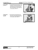
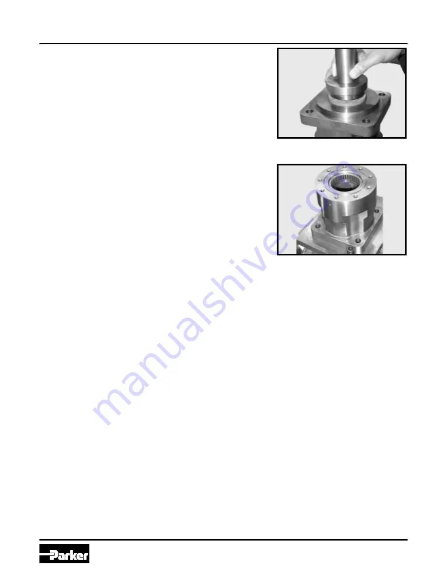
Press in dirt &
water seal

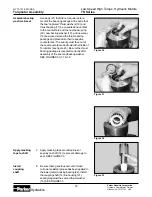
3.

Press a new dirt and water seal (23) into the
housing (21) outer bearing counterbore.  The
dirt and water seal (23) must be pressed in
with the lip facing out and until the seal is
flush to .020 inches (.51 mm) below the end
of housing. SEE FIGURE 28.

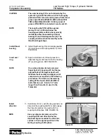
4.

Place housing (21) assembly into a soft
jawed vise or similar support with the cou-
pling shaft bore down, clamping against the
mounting flange. SEE FIGURE 29.

Place housing
assembly
into vice

Figure 29

Figure 28

Torqmotor Assembly

Summary of Contents for TK Series

Page 1: ...HY13 1518 M1 USA TK Series Service Procedure Hydraulics Effective July 2001 Low Speed High Torque Hydraulic Motors ...

Page 2: ...rrent product catalog Due to the variety of operating conditions and applications for these products or systems the user through its own analysis and testing is solely responsible for making the final selection of the products and systems and assuring that all performance safety and warning requirements of the application are met The products described herein including without limitation product f...

Page 3: ...airing and servicing the complete line of Parker TK Torqmotor Units However despite the care and effort taken in preparing this general Service Manual Parker makes no warranties that a the Service Manual or any explanations illustrations information techniques or tools described herein are either accurate complete or correct as applied to a specific Torqmotor unit or b any repairs or service of a ...

Page 4: ... more consistent volumetric efficiency Heavy duty spline geometry Flow thru lubrication provides cooling extending motor life Full interchangeability with other motors which are designed according to industry standards Compatible with most hydraulic systems with regard to pressure torque and speed A unique high pressure shaft seal that eliminates the need for case drains Up to 73 horsepower output...

Page 5: ... in detail the procedure you should follow Column 3 illustrates this procedure with photographs Read all material carefully and pay special attention to the notes cautions and warnings A page with the Torqmotor exploded assembly view is provided several places in this manual The component part names and item numbers assigned on this ex ploded assembly view correspond with names and item numbers in...

Page 6: ... parts or slipping belts Hydraulic Components If you think the problem is caused by a hydraulic component start by checking the easy to reach items Check all hoses and lines for cracks hardening or other signs of wear Reroute any usable hoses that are kinked severely bent or that rest against hot engine parts Look for leaks especially at couplings and fittings Replace any hoses or lines that don t...

Page 7: ...eakage 3 Severely worn or damaged internal splines 4 Excessive heat a Check for faulty relief valve and adjust or replace as required b Check for and repair worn pump c Check for and use correct oil for temperature of operation Replace worn rotor set by disassembling Torqmotor unit Replace rotor set drive link and coupling shaft by disassembling Torqmotor unit Locate excessive heat source usually ...

Page 8: ...ch or hose fitting wrenches SAE 10W40 SE or SF oil Special bearing mandrel for TK Torqmotor SEE FIGURE 1 Feeler gage 005 inch 13 mm TK Torqmotor requires blind hole bearing puller for a 1 750 inch dia 44 45 mm and 2 750 inch dia 69 85 mm bearings Clean corrosion resistant grease Part 406018 is included in each seal kit Recommended grease is Parker Specification 045236 or Mobil Mobilith SHC 460 NOT...

Page 9: ...2 3 86 1 622 41 20 160 4 06 1 983 50 37 296 7 52 1 985 50 42 304 7 72 2 120 53 85 460 11 68 2 122 53 90 470 11 94 2 233 56 72 500 12 70 2 235 56 77 585 14 86 2 483 63 07 595 15 11 2 485 63 12 660 16 76 2 500 63 5 675 17 15 2 88 73 2 1 058 26 87 Torque Chart Part Name Item Number Torque bolt 3 8 24 UNF 2A 1 45 55 ft lbs 60 76 N m nut 1 1 4 18 UNEF 2B 14b 350 450 ft lbs 475 610 N m Fabricate if cons...

Page 10: ...y Item No Description 1 Special Bolt 2 Endcover 3 Seal Ring Commutator 4 Commutator 5 Seal Ring 6 Manifold 7 Retaining Ring 8 Rotor Washer 9 Rotor Set 9a Rotor 9b Stator 9c Vane 9 10 Wear Plate 11 Drive Link 12 Retaining Washer 13 Thrust Bearing 14 Coupling Shaft 14a Key 14b Nut 15 Radial Bearing 16 Thrust Washer 17 Thrust Bearing 18 Shaft Seal 19 Back Up Washer 20 Back Up Ring 21 Housing 22 Radia...

Page 11: ...t using the Torqmotor for assembly numbers not listed below EXPLODED VIEW ITEM 4 6 10 13 15 16 17 19 20 22 23 MANIFOLD WEAR THRUST INNER THRUST THRUST BACKUP BACKUP OUTER DIRT WATER DESCRIPTION COMMUTATOR SEE NOTE PLATE BEARING BEARING WASHER 2 BEARING WASHER RING BEARING SEAL TK Service Part TK014000 TK015000 477983 070029 073007 069033 2 070028 028549 032851 070027 478082 SERIES EXPLODED VIEW IT...

Page 12: ... from system drain it of fluid and take it to a clean work surface Clean and dry the Torqmotor before you start to disassemble the unit As you disassemble the Torqmotor clean all parts except seals in clean petroleum based solvent and blow them dry WARNING petroleum base solvents are flammable Be extremely careful when using any solvent Even a small explosion or fire could cause injury or death WA...

Page 13: ...21 mounting flange WARNING IF THE TORQMOTOR IS NOT FIRMLY HELD IN THE VISE IT COULD BE DISLODGED DURING THE SERVICE PROCEDURES CAUSING INJURY Scribe alignment mark 2 Scribe an alignment mark down and across the Torqmotor components from end cover 2 to housing 21 to facilitate reassembly orientation where required SEE FIGURE 2 Remove special bolts inspect bolts 3 Remove the nine special hex head bo...

Page 14: ...gure 7 Figure 8 Remove end cover inspect bolts 4 Remove end cover 2 and seal ring 5 Discard seal ring SEE FIGURE 5 Wash inspect end cover NOTE 6 Thoroughly wash end cover 2 in proper solvent and blow dry Be sure the end cover flow areas are free of contamination Inspect end cover for cracks and the bolt head recesses for damage Replace end cover as necessary SEE FIGURE 6 A polished pattern not scr...

Page 15: ...E FIGURE 10 The drive link 11 may come away from the coupling shaft 14 with the rotor set and wearplate You may have to shift the rotor set on the wearplate to work the drive link out of the rotor 9a and wearplate Inspect the rotor set in its assembled form for nicks scoring or spalling on any surface and for broken or worn splines If the rotor set component requires replacement the complete rotor...

Page 16: ...ck the rotor lobe to roller vane clearance with a feeler gage at this common centerline If there is more than 005 inches 0 13 mm of clearance replace rotor set SEE FIGURE 11 NOTE If rotor set 9 has two stator halves 9b check the rotor lobe to roller vane clear ance at both ends of rotor Remove inspect drive link 12 Remove drive link 11 from coupling shaft 14 if it was not removed with rotor set an...

Page 17: ...ill attached to the shaft Remove inspect coupling shaft 15 Remove coupling shaft 14 by pushing on the output end of shaft SEE FIGURE 14 Inspect coupling shaft bearing and seal surfaces for spalling nicks grooves severe wear or corrosion and discoloration Inspect for damaged or worn internal and external splines or keyway SEE FIGURE 15 Replace coupling shaft if any of these conditions exist NOTE NO...

Page 18: ...hers SEE FIGURE 16 Remove dirt water seal 19 Remove housing 21 from vise invert it and remove and discard seal 23 A blind hole bearing or seal puller is required SEE FIGURE 17 Inspect housing assembly 20 Inspect housing 21 assembly for cracks the machined surfaces for nicks burrs brinelling or corrosion Remove burrs that can be removed without changing dimensional characteristics Inspect tapped ho...

Page 19: ... and orbit freely All rollers and thrust washers must be free of brinelling and corrosion NOTE The depth or location of bearing 15 in relation to the housing wear plate surface should be measured and noted before removing the bearings This will facilitate the correct reassembly of new bearings SEE FIGURE 19 Remove bearings thrust washers 22 If the bearings or thrust washers must be replaced use a ...

Page 20: ...ith compressed air Remove any paint chips from mating surfaces of the end cover commutator set manifold rotor set wear plate and housing and from port and sealing areas WARNING WARNING SINCE THEY ARE FLAMMABLE BE EXTREMELY CAREFUL WHEN USING ANY SOLVENT EVEN A SMALL EXPLOSION OR FIRE COULD CAUSE INJURY OR DEATH WEAR EYE PROTECTION AND BE SURE TO COMPLY WITH OSHAOR OTHER MAXIMUM AIR PRESSURE REQUIR...

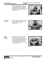
Page 21: ...tionship to adjacent compo nents when assembled SEE FIGURE 24 CAUTION Because bearings 15 and 22 have a press fit into the housing they must be discarded when removed They must not be reused Press in inner bearing 2 The Large Frame TK SeriesTorqmotor housing 21 requires that you assemble a new backup washer 19 new seal 18 with the lip facing to the inside of Torqmotor see figure 45 new thrust wash...

Page 22: ...to the housing 21 outer bearing counterbore The dirt and water seal 23 must be pressed in with the lip facing out and until the seal is flush to 020 inches 51 mm below the end of housing SEE FIGURE 28 4 Place housing 21 assembly into a soft jawed vise or similar support with the cou pling shaft bore down clamping against the mounting flange SEE FIGURE 29 Place housing assembly into vice Figure 29 ...

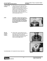
Page 23: ...ment of the bearing package will require that the two captured thrust washers 16 and thrust bearing 17 be unseated and vertical to the counterbore and the new backup ring 20 new backup washer 19 and new seal 18 be worked around the thrust bearing package and placed into their respective counterbores The seal lip must face out of the seal counterbore and toward the inside of Torqmotor see figure 45...

Page 24: ... packet of grease P N 406018 is included in each seal kit NOTE The coupling shaft 14 will be approxi mately 10 inch 2 54 mm below the housing wear plate surface when correctly installed to allow the assembly of thrust bearing 13 and retaining washer 12 The coupling shaft must rotate smoothly on the thrust bearing package Install thrust bearing 9 Install thrust bearing 13 and retaining washer 12 on...

Page 25: ...manifold 6 is made up of several plates bonded together permanently to form an integral component The manifold surface that must contact the rotor set has it s series of irregular shaped cavities on the largest circumference or circle around the inside diameter The polished impres sion left on the manifold by the rotor set is another indication of which surface must contact the rotor set Assemble ...

Page 26: ...annifin Corporation Hydraulic Pump Motor Division Greeneville TN 37745 USA Hydraulics 26 Assemble end cover 22 Assemble end cover over the commutator and in line with the alignment marks on the exterior of the motor SEE FIGURE 40 and 41 Figure 40 Figure 41 Torqmotor Assembly ...
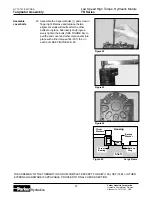
Page 27: ...IS NOW COMPLETE EXCEPT FOR KEY 14A NUT 14B or OTHER EXTERNAL HARDWARE IF APPLICABLE PROCEED TO FINAL CHECKS SECTION Figure 45 Large Frame Figure 44 Figure 43 Assemble cover bolts 23 Assemble the 9 special bolts 1 and screw in finger tight Remove and replace the two alignment studs with bolts after the other bolts are in place Alternately and progres sively tighten the bolts SEE FIGURE 44 to pull t...

Page 28: ...B cast under it is for counter clockwise coupling shaft rotation Use test stand if available to check operation of the Torqmotor Hydraulic Fluid Keep the hydraulic system filled with one of the following 10W40 SE or SF manufacturers suggested oil Hydraulic fluid as recommended by equipment manufacturer but the viscosity should not drop below 50 SSU or contain less than 125 zinc anti wear additives...

Page 29: ...nvestigate and correct any external leak in the hydraulic system no matter how minor the leak Comply with manufacturer s specifications for cleaning or replacing the filter CAUTION Do not weld braze solder or any way alter any Torqmotor component CAUTION Maximum operating pressure must not exceed recommended Torqmotor pressure capacity CAUTION Always carefully inspect any system component that may...

Page 30: ...HY13 1518 M1 USA Low Speed High Torque Hydraulic Motors TK Series Parker Hannifin Corporation Hydraulic Pump Motor Division Greeneville TN 37745 USA Hydraulics 30 Notes ...

Page 31: ... fires floods delays or failures in delivery of carriers or suppliers shortages of materials and any other cause beyond Seller s control 12 Entire Agreement Governing Law The terms and conditions set forth herein together with any amendments modifications and any different terms or conditions expressly accepted by Seller in writing shall constitute the entire Agreement concerning the items sold an...

Page 32: ...Parker Hannifin Corporation 2745 Snapps Ferry Road Greeneville TN 37745 USA Tel 423 639 8151 Fax 423 787 2418 Web Site http www parker com pumpmotor Pinnacle Printing 3M 7 2001 Hydraulics ...

Reviews: