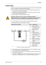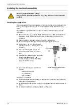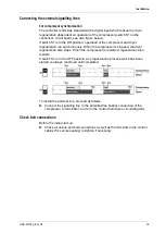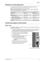
Overview of operating and control elements
28
HDK-MT350_EN_04
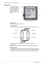
Display panel
The display panel at the
switchbox is equipped
with LEDs (light emitting
diodes) and a digital
display, indicating the
operating status of the
dryer:
Display panel at the switchbox
LED Power (1)
LED is on when dryer is switched on.
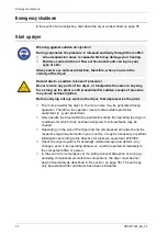
Flow diagram (2)
The current operating phases of the dryer are indicated by means of 4 LEDs:
Vessel B1:
Vessel B2:
Regeneration 1
Regeneration 2
Adsorption 1
Adsorption 2
Depending on the operating phase, the following LEDs might be on
simultaneously:
Adsorption B1
and
regeneration B2
or
regeneration B1
and
adsorption B2
.
Digital display (3)
The digital display shows the individual programme steps and the respective
remaining time. For details regarding the sequence of the individual processing
steps and their duration, please refer to the logic control diagram, page 52.


