background image

55

Drilling, milling and grinding motors 

P1V-S

07.10

www.parker.com/euro_pneumatic

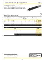
Drilling motor P1V-S040M

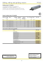
Drilling motor P1V-S025M

G1/4

0,8

5

27

A

B

Ø38 e8

Ø38 d9

34

34

SW

17

M35 x 0,75

M4 x 

4

Ø30

Ø3

8

15

28

Ø

20

e8

G1/2

G1/4

62

26

R1

8

29,5

Ø2

5

G1/4

30

63,5

69

Ø3

4

Ø3

5


B

P1V-S05M0H00, P1V-S05M0480, P1V-S05M050   

141 


65

P1V-S05M0140, P1V-S05M0070, P1V-S05M0035   

157 


81

Clamping area

Inlet

Outlet

Outlet connection 
straight 
P1V-6/313179A

Outlet hose  
P1V-6/806110

Inlet hose   
Ø12/6

For drill chuck B12

Drill chuck 
Dimensions 0,8 - 10 mm
P1V-6/804650

Outlet connection parallel
P1V-6/388378A

Quick-release chuck
Dimensions 0,5 - 8 mm
(max 5000 rpm)
P1V-6/804661

0,8

5

64

150

Ø12,2

Ø

20

e8

SW34

Ø38 e8

Ø38 d9

34

SW

17

G1/4

M35 x 0,75

M

4

x

4

Ø30

G1/2

G1/4

62

26

R18

29,5

63,5

69

Ø2

5

26,5

Ø3

8

Ø3

4

Ø3

5

15

28

G1/4

30

Drill chuck 
Dimensions 0,8 - 10 mm
P1V-6/804650

Quick-release chuck
Dimensions 0,5 - 8 mm
(max 5000 rpm)
P1V-6/804661
(cannot be used for  
P00V-S040M0H00)

Inlet

Outlet

For drill chuck B12

Outlet connection 
straight
P1V-6/3131179A

Outlet connection parallel
P1V-6/388378A

Inlet hose
Ø12/6

Outlet hose
P1V-6/806110

Clamping area

CAD drawings on the Internet

Our home page www.parker.com/euro_pneumatic  
includes the AirCad Drawing Library with D and  
3D drawings for the main versions.

Summary of Contents for 1P1V-S020A00005

Page 1: ...rotary actuators Stainless steel air motors 0 02 1 2 kW Stainless steel air motors 0 02 1 2 kW P1V S P1V S Stainless Steel Air Motors FLUIDTECHNIK BOHEMIA s r o Olomouck 87 tel 548 213 233 235 CZ 627...

Page 2: ...aspects of your application and review the information concerning the product or system in the current product catalog Due to the variety of operating conditions and applications for these products or...

Page 3: ...sions for Motor and Brackets Motor P1V S002 36 Motor P1V S008 36 Motor P1V S012 37 Motor P1V S020 38 Motor P1V S030 39 Motor P1V S060 40 Motor P1V S120 41 Brake motor P1V S020 42 Brake motor P1V S030...

Page 4: ...cal shape there are no pockets which can accumulate dirt or bacteria Addition ally the two halves of the motor body are sealed with an Fluor rubber seal Planetary gear Fluor rubber O ring Lubrication...

Page 5: ...ors can be used in the harshest environments Most P1V S motors are ATEX certified The shape design and non lubricated operation allow the motor to be suitable for use in the food industry Air motors c...

Page 6: ...gh the residual port The residual port doubles as the pressure port when the motor is operated in the reverse direction Inlet Inlet left Residual outlet Inlet right 1 Rotor cylinder 2 Rotor 3 Vanes 4...

Page 7: ...we get a lower torque at any given speed than would be developed at full air flow Pressure regulation The speed and torque can also be regulated by installing a pressure regulator in the inlet pipe W...

Page 8: ...onic PVL C 5 3 vented centre 8 mm push in 840 Valvetronic PVL C 5 2 G1 4 840 Flowstar P2V B 1090 ISOMAX DX1 1150 B53 Manual and mechanical 1160 B4 Series 1170 VIKING Xtreme P2LBX 1290 B5 Series G1 4 1...

Page 9: ...0 6 3 8 0 Air flow required Nl min 230 300 380 480 Min internal diameter of pipe mm 4 6 6 10 Choice of air treatment unit recommended min air flow in litres minute at 7 5 bar air supply and 0 8 bar p...

Page 10: ...as standard which is the most common application of air motors The motor is also available with optional hard vanes for continuous lubrication free opera tion option C The P1V S motor is equipped as s...

Page 11: ...ure Vessels Directive Low Voltage Directive ATEX Directive ATEX ATmosphere EXplosive X The specified hours of operation apply when the motor is running at the speed corresponding to maximum power load...

Page 12: ...mum torque of each motor at maximum output Add your operating point to the graph then select a marked point above and to the right of your point Then use the correct working diagram of the chosen moto...

Page 13: ...1 9 P1V S020A0006 10 P1V S020A0005 P1V S020D0005 11 P1V S020A0002 12 P1V S020A0001 13 P1V S020A00005 Graphs for each motor see page 25 1 P1V S030A0E50 P1V S030D0E50 2 P1V S030A0460 P1V S030D0460 3 P1V...

Page 14: ...tion With lubrication these motors can operation 100 of the time Z Spring loaded standard vanes Standard vanes These motors are of the vane type for inter mittent lubrication free operation They can o...

Page 15: ...030 300 W 060 600 W 120 1200 W Optional functions 0 Standard C Continuous lubrication free operation Z Spring loaded vanes M Multi combination of C Z D Standard with brake E Option C with brake F Opti...

Page 16: ...ese zones The table below describes the zones in an installation where there is a potential for explosive atmospheres The owner of the installation must analyse and assess the area in which the explos...

Page 17: ...G D G D Zone 0 20 1 21 2 22 Declaration of conformity The product catalogues contain copies of the declaration of conformity demonstrating that the product meets the requirements of directive 94 9 EC...

Page 18: ...class Max surface temperature 1 When installing the motor is it certain that there is no potentially explosive atmosphere oil acids gases vapours or radiation 2 Is the ambient temperature as specified...

Page 19: ...been tested to ensure that the maximum is 80 C This provides a safety margin of 5 K T5 If equipment is in temperature class T5 the maximum surface temperature must not exceed 100 C To guarantee this t...

Page 20: ...ane options C Z or M The P1V S002A and P1V S008A require oil mist for lubricating the gearbox NOTE All technical data is based on a working pressure of 6 bar Installation brackets see page 35 Dimensio...

Page 21: ...ue Nm P power W P1V S008A0N00 M torque Nm P power W 4000 16000 24000 20 40 60 80 0 06 0 12 M P 400 800 1200 1600 2000 20 40 60 80 0 4 0 8 1 2 1 6 M P P1V S008A0190 M torque Nm P power W P1V S008A0130...

Page 22: ...Speed at Torque Min Air con Conn Min pipe Weight Order code speed max at max start sumption at ID power power torque max power kW rpm rpm Nm Nm l s mm Kg 0 120 22000 11000 0 10 0 15 5 0 G1 8 6 0 350...

Page 23: ...5 15 45 75 105 30 60 90 120 5 10 15 20 M P P1V S012A0360 P1V S012D0360 M torque Nm P power W P1V S012A0140 P1V S012D0140 M torque Nm P power W P1V S012A0090 P1V S012D0090 M torque Nm P power W P1V S01...

Page 24: ...0 6 3 G1 8 10 1 050 P1V S020A00005 Max permitted torque Data for reversible air motor with threaded shaft P1V S020D series Max power Free Speed at Torque Min Air con Conn Min pipe Weight Order code sp...

Page 25: ...00 6 12 18 24 M P 40 60 20 80 100 140 160 200 120 180 2 5 5 0 7 5 10 0 12 5 15 0 17 5 20 0 M P 25 75 125 175 50 100 150 200 60 30 90 120 150 25 75 125 175 50 100 150 200 15 30 45 60 M P n speed rpm n...

Page 26: ...motor with threaded shaft P1V S030D series Max power Free Speed at Torque Min Air con Conn Min pipe Weight Order code speed max at max start sumption at ID power power torque max power kW rpm rpm Nm...

Page 27: ...0 0 2 0 4 0 6 0 8 M P 300 100 200 0 6 1 2 1 8 2 4 M P 2000 1000 3000 4000 5000 300 100 200 1 0 2 0 3 0 4 0 M P 1000 500 1500 2000 2500 300 100 200 2 0 4 0 6 0 8 0 M P 600 300 900 1200 1500 300 100 200...

Page 28: ...0400 0 600 2700 1350 4 20 6 40 14 5 G3 8 12 2 100 P1V S060A0270 0 600 1700 850 6 70 10 10 14 5 G3 8 12 2 100 P1V S060A0170 0 600 720 360 15 90 24 00 14 5 G3 8 12 2 200 P1V S060A0072 0 600 480 240 23 9...

Page 29: ...8 12 16 M P 600 1200 1800 600 200 400 10 20 30 40 M P 250 500 750 600 200 400 10 20 30 40 M P 100 200 500 300 400 600 200 400 20 40 60 80 M P 100 200 300 400 300 100 200 60 120 180 240 M P 20 40 60 8...

Page 30: ...S120A0800 1 200 2700 1350 8 50 12 70 27 G3 4 19 5 5 P1V S120A0270 1 200 1100 550 21 00 31 00 27 G3 4 19 5 5 P1V S120A0110 1 200 780 390 29 40 44 00 27 G3 4 19 5 6 P1V S120A0078 1 200 320 160 71 60 107...

Page 31: ...ed rpm n speed rpm n speed rpm n speed rpm 1200 400 800 1 5 3 0 4 5 6 0 M P 2000 4000 6000 8000 1200 400 800 4 8 12 16 M P 1000 2000 3000 1200 400 800 10 20 30 40 M P 400 800 1200 1200 400 800 15 30 4...

Page 32: ...Warning If the number of braking operations is exceeded the degree of wear might be greater than permitted and the braking effect might be lost If this happens you simply need to replace the worn brak...

Page 33: ...0 5 40 8 20 6 3 G1 8 10 1 150 P1V S020AD070 0 200 350 160 12 00 18 00 6 3 G1 8 10 1 150 P1V S020AD035 0 100 180 90 10 50 15 00 4 5 G1 8 10 1 150 P1V S020AD018 0 200 110 55 33 00 49 50 6 3 G1 8 10 3 30...

Page 34: ...3 60 8 0 G1 4 10 1 400 P1V S030AD240 0 300 1400 700 4 10 6 10 8 0 G1 4 10 1 450 P1V S030AD140 0 300 600 300 9 60 14 30 8 0 G1 4 10 1 500 P1V S030AD060 0 300 280 140 20 50 26 00 8 0 G1 4 10 1 500 P1V...

Page 35: ...1V S008 P1V S008 0 08 P1V S4008F P1V S012 0 09 P1V S4012F P1V S020 P1V S025 0 11 P1V S4020F P1V S020A0011 0 55 P1V S4020C P1V S020A0006 P1V S030A0023 P1V S030A0010 P1V S030 P1V S040 0 11 P1V S4030F P1...

Page 36: ...2 13 H8 20 30 5 5 4 40 50 25 M8 x 0 75 M8 x 0 75 M8 x 0 75 L R 13 12 2 50 100 123 5 6 2 7 5 22 d9 SW20 M3 13 e8 6 k6 15 5 0 1 Clamping area Inlet anticlockwise Inlet clockwise Outlet 132 5 13 5 10 70...

Page 37: ...8 5 50 40 50 13 H8 4 5 42 0 2 25 5 5 4 5 20 30 Flange bracket for motor P1V S012 P1V S4012B Foot bracket for motor P1V S012 P1V S4012F M4x4 5 21 L R 6 8 6 8 4 7 9 G1 8 G1 8 1 G1 8 13 e8 SW2 4 27 e8 27...

Page 38: ...tor P1V S020 P1V S4020B Foot bracket for motor P1V S020 P1V S4020F 19 7 8 G1 8 G1 8 G1 4 M4x4 30 20 e8 SW 3 4 38 e8 38 d9 3 4 8 A 0 8 8 5 B A3x3x18 DIN 6885 23 10 k6 3 8 24 U NF 26 16 5 15 14 24 Clamp...

Page 39: ...32 0 159 82 30 14 A5x5x20 DIN 6885 P1V S030A0028 P1V S030D0028 32 0 159 82 30 14 A5x5x20 DIN 6885 P1V S030A0018 P1V S030D0018 32 0 159 82 30 14 A5x5x20 DIN 6885 P1V S030A0005 P1V S030D0005 32 0 164 8...

Page 40: ...4 30 14 A5x5x20 DIN 6885 P1V S060A0170 194 162 62 4 30 14 A5x5x20 DIN 6885 P1V S060A0072 212 180 62 4 30 14 A5x5x20 DIN 6885 P1V S060A0048 212 180 80 4 30 19 A6x6x22 DIN 6885 P1V S060A0030 217 180 80...

Page 41: ...5 205 10 73 A8x7x50 DIN 6885 28 k6 10 82 e9 60 68 M8x14 20 M10 1 5 Motor P1V S120 P1V S120A0800 P1V S120A0270 P1V S120A0110 P1V S120A0078 P1V S120A0032 P1V S120A0012 Flange bracket for motor P1V S120...

Page 42: ...G1 8 G1 4 M4x4 30 20 e8 SW 3 4 38 e8 38 d9 3 4 8 24 A 0 8 5 B A3x3x18 DIN 6885 23 10 k6 M5 Clamping area Inlet Inlet Outlet Stainless key P1V S020AD with shaft with keyed shaft P1V S020DD with threade...

Page 43: ...4 A5x5x20 DIN 6885 P1V S030AD028 32 0 202 82 30 14 A5x5x20 DIN 6885 P1V S030AD005 32 0 207 82 30 14 A5x5x20 DIN 6885 Flange bracket for motor P1V S030 P1V S4030B Foot bracket for motor P1V S030 P1V S4...

Page 44: ...s A slow and even feed movement is necessary in machining applications During drilling the feed must not uncontrollably speed up once the drill breaks through the material One good way of solving the...

Page 45: ...to 500 N mm 28 m min 8800 4400 3000 2200 1800 1500 1300 1100 975 880 Unalloyed steel from 500 to 700 N mm 25 m min 7800 3900 2600 2000 1600 1300 1100 975 865 780 Unalloyed steel over 700 N mm 14 m mi...

Page 46: ...4o 6 0 38 P1V S017N0Q00 0 170 6000 Collet chuck 6 mm 3 5 5 0 G1 4o 6 0 38 P1V S017N0600 0 170 4000 Collet chuck 6 mm 4 6 5 0 G1 4o 6 0 38 P1V S017N0400 0 170 1500 Collet chuck 6 mm 4 6 5 0 G1 4o 6 0 3...

Page 47: ...mm l s mm Kg 0 170 6000 For drill chuck B10 3 5 5 0 G1 4o 6 0 38 P1V S017M0600 0 170 4000 For drill chuck B10 4 6 5 0 G1 4o 6 0 38 P1V S017M0400 0 170 1500 For drill chuck B10 4 6 5 0 G1 4o 6 0 38 P1V...

Page 48: ...17000 Collet chuck 6 mm 6 6 3 G1 4o 6 0 80 P1V S025N0H00 0 250 4800 Collet chuck 6 mm 4 6 6 3 G1 4o 6 0 80 P1V S025N0480 0 250 2500 Collet chuck 6 mm 6 6 6 3 G1 4o 6 0 80 P1V S025N0250 0 250 1400 Coll...

Page 49: ...0 250 17000 For drill chuck B12 6 6 3 G1 4o 6 0 80 P1V S025M0H00 0 250 4800 For drill chuck B12 4 6 6 3 G1 4o 6 0 80 P1V S025M0480 0 250 2500 For drill chuck B12 6 8 6 3 G1 4o 6 0 80 P1V S025M0250 0...

Page 50: ...0 400 17000 For drill chuck B12 6 8 0 G1 4o 6 0 80 P1V S040M0H00 0 400 4800 For drill chuck B12 4 6 8 0 G1 4o 6 0 80 P1V S040M0480 0 400 2500 For drill chuck B12 6 8 8 0 G1 4o 6 0 80 P1V S040M0250 0 4...

Page 51: ...ill dia milldia max power kW rpm max mm max mm l s mm Kg 0 400 20000 Collet chuck 8 mm 8 10 5 0 G1 4o 6 0 80 P1V S040N0L00 Accessories for drilling motor P1V S040N Name Order code Collet chucks Collet...

Page 52: ...e Version Point grinding diam Milling diam Air con Conn Min pipe Weight Order code speed max max sumption at ID max power kW rpm mm mm l s mm Kg 0 090 100000 Collet chuck 3 mm 5 3 2 0 Pipe 6 4 4 0 3 P...

Page 53: ...07 105 Clamping area Outlet Collet chuck 3 Inlet 200 167 118 33 22 11 SW9 SW10 12 25d10 SW13 13 8 G1 4 24 9 14 47 22 2 m G1 2 Clamping area Collet chuck 6 Inlet Outlet Outlet hose P1V 6 806112 Seal fo...

Page 54: ...Outlet connection parallel P1V 6 302923A Drill chuck Dimensions 0 5 6 mm P1V 6 804655 For drill chuck B10 G1 4 SW9 12 SW10 0 8 5 28 A B 38 e8 38 d9 34 34 SW17 M35 x 0 75 M 4 x 4 30 38 15 28 20 e8 G1...

Page 55: ...6 804650 Outlet connection parallel P1V 6 388378A Quick release chuck Dimensions 0 5 8 mm max 5000 rpm P1V 6 804661 0 8 5 64 150 12 2 20 e8 SW34 38 e8 38 d9 34 SW17 G1 4 M35 x 0 75 M 4 x 4 30 G1 2 G1...

Page 56: ...0 30 91 179 3 x 45 38 e8 19 38 15 28 G1 2 G1 4 62 26 R18 29 5 25 G1 4 30 Clamping area Outlet Inlet Outlet connection straight P1V 6 313179A Inlet hose 12 6 Outlet hose P1V 6 806110 Outlet connection...

Page 57: ...rota tional force or the force applied in the opposite direction It is the product of the rotational force F and the distance from the pivot point radius or moment arm Formula M m x g x r M torque in...

Page 58: ...Material Coefficient of kinetic friction Dry Lubricated Bronze Bronze 0 2 0 06 Bronze Grey iron 0 21 0 08 Grey iron Grey iron 0 12 Steel Bronze 0 18 0 07 Steel Ice 0 014 Steel Grey iron 0 16 0 05 Ste...

Page 59: ...e total force required in order to move the object in N Fkinetic resistance total kinetic resistance in N Facc acceleration force in N m mass in kg a acceleration in m s2 A carriage weighing 2500 kg i...

Page 60: ...18 P1V S060A0030 1130 2090 18 P1V S060A0010 1130 2090 18 P1V S120A0800 2330 2260 18 P1V S120A0270 2330 2260 18 P1V S120A0110 2330 2260 18 P1V S120A0078 2330 2700 30 P1V S120A0032 2330 2700 30 P1V S12...

Page 61: ...380 50 25 P1V S025N 750 260 25 Drilling motors with drill chuck Order code Fax Frad a N N mm P1V S017M 380 35 60 P1V S025M 380 150 70 P1V S040M 750 150 70 Milling motor Order code Fax Frad a N N mm P1...

Page 62: ...613 P1V S120AC270 9121720613 P1V S120AC110 9121720613 P1V S120AC078 9121720614 P1V S120AC032 9121720614 P1V S120AC012 9121720614 Service kit vanes for intermittent lubrication free operation For motor...

Page 63: ...9121720620 P1V S120AZ078 9121720621 P1V S120AZ032 9121720621 P1V S120AZ012 9121720621 Service kit spring loaded vanes for continuous lubrica tion free operation Option M For motor Order code P1V S012A...

Page 64: ...S025N M P1V 6 446087A P1V S040M P1V 6 446088A For milling motor Order code P1V S040N P1V 6 446088A For grinding motor Order code P1V S020N P1V 6 446090A Service kits for drilling milling and grinding...

Page 65: ...ure that the pressure supplied to the inlet port of the motor is correct in order to allow the motor to work at maximum capacity If the valve supplying a large motor is too small or if the supply line...

Page 66: ...66 Stainless Steel Air Motors P1V S...

Page 67: ......

Page 68: ...NAD METUJ Vrchoviny 29 549 01 tel fax 491 472 844 tel 491 472 328 OPAVA Hradeck 668 1 746 01 tel 553 770 911 fax 553 770 912 LOUNY Vladim rsk 2457 440 01 tel fax 415 658 703 PLZE Brojova 16 326 00 tel...

Reviews: