background image

404XE Series Product Manual


13


Parker Hannifin Corporation


EMN Automation 

-

 Parker


Irwin, Pennsylvania


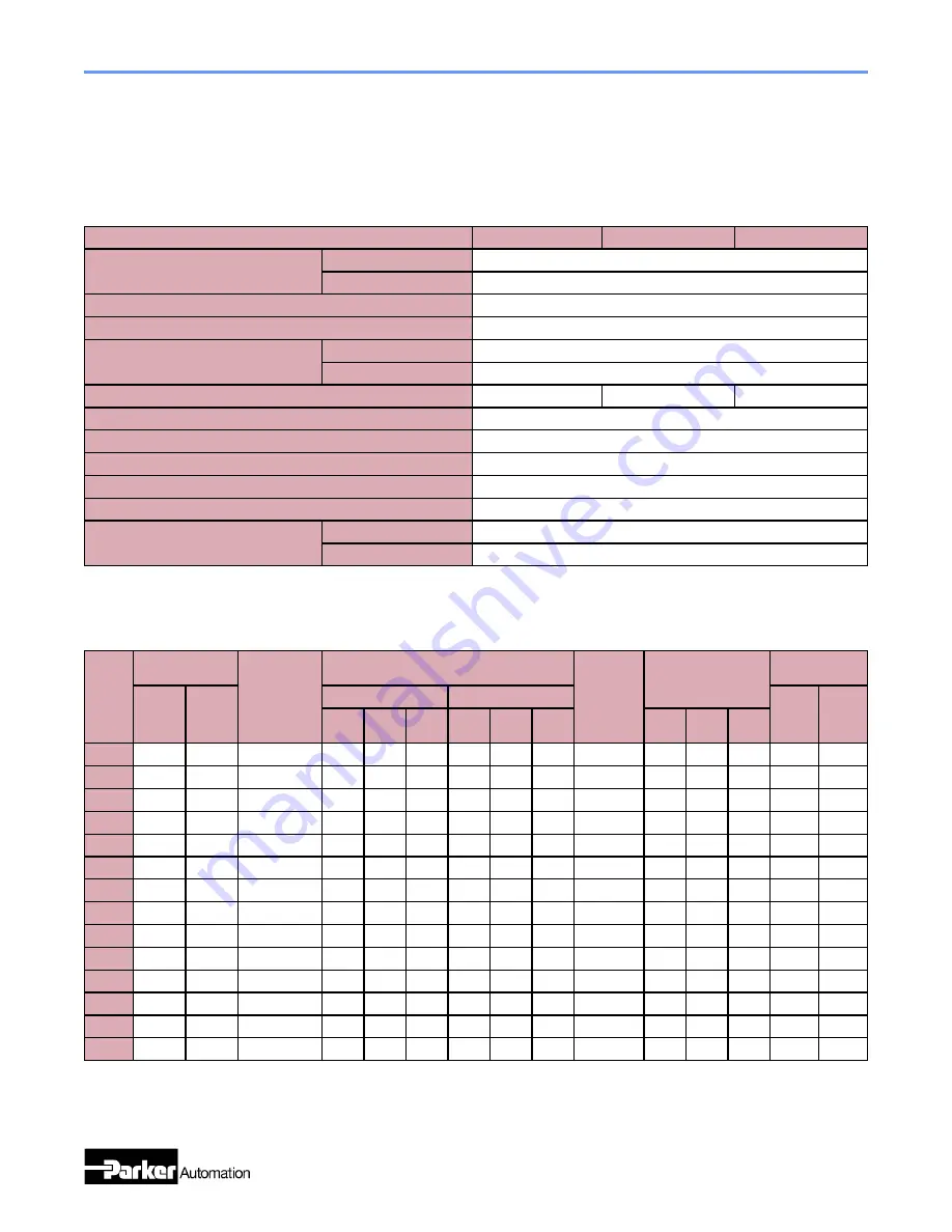
404XE Common Performance Characteristics


5mm Lead (D2 Option)


10mm Lead (D3 Option)


20mm Lead (D4 Option)


Bidirectional Repeatability 

-

 µm


T01 to T11 Option


+/

-

 10


T12 to T15 Option


+/

-

 15


Duty Cycle


100% 


Max Acceleration

(1)


-

 m/s

2

 (in/s

2

)


20 (787) 


Normal Load Capacity

(2) 

-

 kgf (lbs)


Short Carriage (NL Option)


61.3 (135) 


Long Carriage (VL Option)


122.6 (270) 


Axial Load Capacity

(1)(2) 

-

 kgf (lbs) 


60 (132)


70 (154)


70 (154)


Drive Screw Efficiency


90% 


Max Breakaway Torque 

-

 Nm (oz

-

in)


0.25 (35)


Max Running Torque (Rated @ 2rps) 

-

 Nm (oz

-

in)


0.21 (30)


Linear Bearing Coefficient of Friction


0.01 


Ballscrew Diameter 

-

 mm (in)


16.0 (0.63)  


Carriage Weight 

-

 kgf (lbs)


Short Carriage (NL Option)


0.215 (0.47)


Long Carriage (VL Option)


0.495 (1.09)


(1)  

Applies to units with long carriage (VL Option).


(2)  

Refer to life/load charts.


Performance Specifications 

-

 404XE


404XE Travel Dependent Performance Characteristics


Travel 

Option 


Travel 


Positional

(3)(4)


Accuracy

-

 µm 


Input Inertia 

-

 10

-

5

 kg

-

m

2


Max Screw 

Speed 

-

 rps 


Max Velocity 

-

 m/s 


Total Table 

Weight 

-

 kgf


NL 

Option


VL  

Option


NL  Option


VL Option


NL 

Option


VL  

Option


5mm 

Lead


10mm 

Lead 


20mm 

Lead 


5mm 

Lead


10mm 

Lead


20mm 

Lead 


5mm 

Lead


10mm 

Lead 


20mm 

Lead 


T01


25 mm


N/A


42


0.81


N/A


N/A


N/A


N/A


N/A


72


0.36


0.73


1.50


1.42


1.70


T02


50 mm


N/A


50


0.94


0.98


N/A


N/A


N/A


N/A


72


0.36


0.73


1.50


1.61


1.89


T03


100 mm


33 mm


58


1.19


1.23


1.12


1.21


1.30


1.40


72


0.36


0.73


1.50


1.95


2.23


T04


150 mm


83 mm


66


1.44


1.48


1.32


1.46


1.55


1.60


72


0.36


0.73


1.50


2.35


2.63


T05


200 mm


133 mm


74


1.69


1.73


1.51


1.71


1.80


1.79


72


0.36


0.73


1.50


2.59


2.87


T06


250 mm


183 mm


82


1.94


1.99


1.70


1.96


2.06


1.99


72


0.36


0.73


1.50


2.97


3.25


T07


300 mm


233 mm


90


2.20


2.24


1.90


2.21


2.31


2.18


72


0.36


0.73


1.50


3.34


3.62


T08


350 mm


283 mm


98


2.45


2.49


2.09


2.47


2.56


2.37


72


0.36


0.73


1.50


3.50


3.78


T09


400 mm


333 mm


106


2.70


2.74


2.29


2.72


2.81


2.57


72


0.36


0.73


1.50


3.83


4.11


T10


450 mm


383 mm


114


2.95


2.99


2.48


2.97


3.07


2.76


72


0.36


0.73


1.50


4.09


4.37


T11


500 mm


433 mm


122


3.21


3.25


2.67


3.22


3.32


2.96


72


0.36


0.73


1.50


4.22


4.50


T12


550 mm


483 mm


130


3.46


3.50


2.87


3.48


3.57


3.15


72


0.36


0.73


1.50


4.55


4.83


T13


600 mm


533 mm


138


3.71


3.75


3.06


3.73


3.82


3.34


69


0.34


0.68


1.32


4.87


5.15


T15


700 mm


633 mm


154


4.21


4.25


3.45


4.23


4.33


3.73


52


0.26


0.52


1.00


5.12


5.40


(3)  

Positional accuracy applies to inline motor configurations only.  Contact factory for parallel motor specifications.  Positional specifications are based on un-

loaded conditions and apply to individual axes only.


(4)  

Consult factory for specifications with linear feedback.


Summary of Contents for 404XE Series

Page 1: ...Parker Automation Manual No 102 0988 01 Rev J 404XE Series Product Manual Effective October 3 2018 Supersedes August 20 2018 Electromechanical Positioning Systems...

Page 2: ...ty and warning requirements of the application are met The products described herein including without limitation product features specifications designs availability and pric ing are subject to chang...

Page 3: ...ns 404XE 13 Test Methodology 14 Techinical Data 404XE 15 Clean Room Preparation 19 CHAPTER 3 COMPONENT SPECIFICATIONS 20 Motor Information 20 Limit Home Switch Information 404XE 20 Encoder Information...

Page 4: ...ed Charts for 402 403XE Page 24 Clarified Lubricant Application for 402 403XE Page 41 Corrected Part Number for 403XE Riser Plate Page 46 Rev 3 October 1 2007 Page 31 Sensor Pack Wiring only Ground Wi...

Page 5: ...it in its application Please observe the following guidelines for handling and mounting of your new positioner DO NOT allow the positioner to drop onto the mounting surface Dropping the positioner can...

Page 6: ...the positioner after high duty operation Motor tempera ture may approach 60 C Electrical Shock DO NOT take apart or touch any internal components of the positioner while unit is plugged into an electr...

Page 7: ...any specification except motion of a standard unit before failure is 5 C to 40 C Specifications Are Mounting Surface Dependent Catalog specifications are obtained and measured when the positioner is f...

Page 8: ...ctor T15 700 633 H11 N C current sinking sensor pack VL carriage D3 D4 drives and Limit Home Sen sor Pack H12 N O current sinking sensor pack option are not offered with T01 travel models H13 N C curr...

Page 9: ...s standard dowel pinned toe clamped to M5 SM16 Parallel mounting A location X axis motor 3 00 M6 SM16 Parallel mounting B location P39 Y axis standard dowel pinned toe clamped to M7 SM16 Parallel moun...

Page 10: ...omation Parker Irwin Pennsylvania Assembly Diagrams 404XE Limit Home Switches Riser Plate Sensor Pack Inline Motor Block Base Hard Cover Motor Adapter Carriage Ballscrew Brake Linear Encoder Rotary En...

Page 11: ...404XE Series Product Manual 11 Parker Hannifin Corporation EMN Automation Parker Irwin Pennsylvania Dimensional Drawings 404XE Visit www parkermotion com for 2D CAD and 3D Models...

Page 12: ...404XE Series Product Manual 12 Parker Hannifin Corporation EMN Automation Parker Irwin Pennsylvania Dimensional Drawings 404XE...

Page 13: ...10mm Lead 20mm Lead T01 25 mm N A 42 0 81 N A N A N A N A N A 72 0 36 0 73 1 50 1 42 1 70 T02 50 mm N A 50 0 94 0 98 N A N A N A N A 72 0 36 0 73 1 50 1 61 1 89 T03 100 mm 33 mm 58 1 19 1 23 1 12 1 21...

Page 14: ...peak error measured by a laser interferometer and prism located at 37 5mm above the center of the table This type of measurement sums the X Y Z roll pitch and yaw errors Temperature deviations from t...

Page 15: ...ds 404XE Table Life with Normal Load 1000 10000 100000 0 100 200 300 400 500 600 700 800 900 1000 1100 1200 Load N Life km Short Carriage NL Option Long Carriage VL Option 404XE Table Life with Pitch...

Page 16: ...hey should be used in conjunction with the corresponding formulas on the following pages also available at www parkermotion com to establish the life relative to load for each bear ing four per table...

Page 17: ...404XE Series Product Manual 17 Parker Hannifin Corporation EMN Automation Parker Irwin Pennsylvania...

Page 18: ...404XE Series Product Manual 18 Parker Hannifin Corporation EMN Automation Parker Irwin Pennsylvania...

Page 19: ...urement location A point directly below a component may have a different particle count than at a side location Cleanroom class compatibility information for 404XE tables with cleanroom preparation R1...

Page 20: ...E Sensor Pack Wiring Code Power Red Limit 1 1 Output Signal Blue Limit 2 1 Output Signal Orange Home Output Signal Green Ground Black Shield Connect to Earth Ground Green w Yellow Stripe 1 Limit 1 is...

Page 21: ...ge 30 C to 110 C Cable Length 0 47 m Cable Material PVC 404XE Rotary Encoder Wiring Code Power Red Pin 1 Ground Black Pin 2 Channel A White Pin 3 Channel A Yellow Pin 4 Channel B Green Pin 5 Channel B...

Page 22: ...r Shaft mm in Outside Diameter mm in Length mm in Rated Torque Nm Torsional Stiffness Nm Clamp Screw Torque in lb Misalignment Radial Axial Angular C2 Oldham 6 3 0 25 25 4 1 00 31 8 1 25 4 75 0 291 0...

Page 23: ...ifications are based on the following conditions The positioner must be bolted down along its entire length The positioner must be mounted to a flat stable surface with flatness error less than or equ...

Page 24: ...lts to be used when mounting payloads to the carriage Excessive length bolts can cause damage or pin the table in position Riser Plates Most of the motors used with the 404XE have a taller profile tha...

Page 25: ...ter 3 for coupling clamp screw torque specifications DO NOT use Loctite on coupling screws If motor has a rear shaft rotate motor by rear shaft and check that carriage moves Hold carriage and attempt...

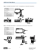
Page 26: ...1 Belt 515 4 M4 x 8 Button Head Screw 517 2 M5 x 10 Button Head Screw 539 4 M3 x 8 Button Head Screw 540 2 M5 x 20 Socket Head Cap Screw 541 4 M4 Ribbed Spring Washer Step 4 IF USING MOTOR POSITION C...

Page 27: ...ecess distance should match the distance recorded earlier Readjust until the distance is matched and tighten clamp screw to 13in lb Note once the Loctite 609 is applied this step should be completed w...

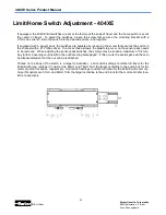
Page 28: ...on the sensor pack needs to be removed When adjusting the sensor pack switches the screws may be turned a maximum of 1 4 turn Any further loosening could result in the nut becoming disengaged If this...

Page 29: ...Amber smooth FOR CLEANROOM PREPARATION R12 R14 OPTION Braycote 803 Translucent white smooth and buttery Maintenance Frequency FOR BOTH STANDARD AND CLEANROOM PREPARATION Linear bearings and ballscrews...

Page 30: ...f Loctite 638 to the counterbore Step 4 Install the wedge into the end of the mandrel and insert mandrel wedge assembly into the drive screw shaft counterbore until the mandrel bottoms out at the shou...

Page 31: ...w shaft counterbore until the mandrel bottoms out at the shoulder Install the long socket head cap screw and tighten Step 11 Orient the encoder so that the mounting holes align with the tapped holes i...

Page 32: ...898 53 404XE Coupling 0 25 Bore Bellows 003 1898 65 404XE Coupling 0 375 Bore Bellows 003 1898 95 404XE Coupling 11mm Bore Bellows 003 2918 01 404XE Limit Home 5m Extension Cable Part Number Descripti...

Page 33: ...404XE Series Product Manual 33 Parker Hannifin Corporation EMN Automation Parker Irwin Pennsylvania See Chapter 2 for motor adapter drawings 002 3619 01 404XE Riser Plate 002 3618 01 404XE Toe Clamp...

Page 34: ...404XE Series Product Manual 34 Parker Hannifin Corporation EMN Automation Parker Irwin Pennsylvania Notes...

Page 35: ...Parker Hannifin Corporation Electromechanical Automation Divi sion 1140 Sandy Hill Road Irwin PA 15642 Tel 800 245 6906 www parkermotion com Email emn_sales parker com emn_support parker com...

Reviews: