404XE Series Product Manual
25
Parker Hannifin Corporation
EMN Automation
-
Parker
Irwin, Pennsylvania
Inline Motor Mounting
Follow the below procedure to install an inline motor to the 404XE linear positioner.
Step 1:
Slide coupling onto positioner drive screw shaft and tighten the clamp screw. See Chapter 3 for cou-
pling clamp screw torque specifications. DO NOT use Loctite on coupling screws.
Step 2:
Mount motor to motor adapter using appropriate hardware, making sure motor shaft engages coupling
bore. Apply Loctite 242 to mounting screw threads prior to assembly.
Step 3:
Tighten coupling clamp screw on motor shaft side. See Chapter 3 for coupling clamp screw torque
specifications. DO NOT use Loctite on coupling screws. If motor has a rear shaft, rotate motor by rear shaft and
check that carriage moves. Hold carriage and attempt to rotate motor by rear shaft to check that coupling does
not slip.
Tools Required:
2.0mm, 2.5mm, 3.0mm, and 4.0mm Hex Wrenches, Torque Wrench, Loctite 242 or Equiva-
lent
Parallel Motor Mounting
-
404XE
Tools Required:
2.0mm, 2.5mm, 3.0mm, and 4.0mm Hex Wrenches, Torque Wrench, Depth Micrometer,
Force Gauge, Loctite 609 and 242 or Equivalent
Step 2:
Remove any motor, coupling, adapter plate, and motor block previously installed on positioner.
Step 1:
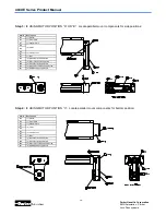
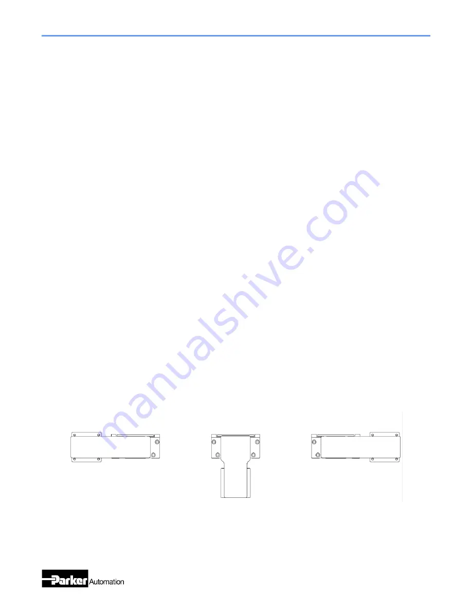
Identify the desired parallel mounting position
“
A
”, “
B
”,
or
“
C
”.
Position A
Position C
Position B
Follow the below procedure to install the parallel motor mount and motor to the 404XE linear positioner.


