404XE Series Product Manual
27
Parker Hannifin Corporation
EMN Automation
-
Parker
Irwin, Pennsylvania
Step 6:
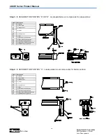
Place shroud, item #125, (less cover plate) over pulley onto positioner in desired orientation. For side
positions
“
A
”
and
“
B
”
install and tighten two (2) socket head cap screws, item #540, through the deep counter-
bored holes and install and tighten two (2) button head screws, item #517, through the remaining holes. For
bottom position
“
C
”
install and tighten four (4) socket head cap screws, item #540, through the deep counter-
bored holes. Prior to assembly apply Loctite 242 to the screw threads.
Step 8:
Mount motor adapter plate, item #127, to motor flange using appropriate hardware. Note the motor side
of the adapter plate is piloted for the motor. Apply Loctite 242 to screw threads prior to assembly. IT IS CRITI-
CAL that the mounting screws do not protrude through the adapter plate.
Step 9:
Apply Loctite 609 to motor shaft and loosely mount pulley, item #128, with clamp collar, item #130, to
motor shaft. Place motor/adapter plate assembly against shroud in the mounting position and measure the dis-
tance from the open face of the shroud to the face of the pulley. The pulley recess distance should match the
distance recorded earlier. Readjust until the distance is matched and tighten clamp screw to 13in
-
lb. Note once
the Loctite 609 is applied, this step should be completed within 10 minutes.
Step 10:
Place drive belt, item #132, over drive screw shaft pulley.
Step 11:
Place motor/adapter plate assembly against shroud and place belt over motor pulley. Loosely install
four (4) button head screws, item #515, with four (4) spring washers, item #541. IT IS CRITICAL that the correct
length bolts be used.
Step 12:
Tension drive belt by applying a side force of 15lbs to the motor and tighten the mounting screws.
Manually traverse the positioner back and forth while observing the belt. The belt should ride in the center of the
pulley surfaces (between the flanges). If the belt continually runs against one side of the pulley then alignment
needs to be readjusted.
Step 7:
Using depth micrometer, measure distance from the open face of the shroud to the face of the pulley
flange. The pulley should be recessed some distance from the open face of the shroud. Record this distance.
Step 13:
Mount cover plate using four (4) button head screws, item #539.
Step 5:
Apply Loctite 609 to positioner drive screw shaft. Mount pulley, item #129, with clamp collar, item #131,
to screw shaft by sliding it onto the shaft until it contacts the locknut. Tighten clamp screw to 13in
-
lb.


