404XE Series Product Manual
28
Parker Hannifin Corporation
EMN Automation
-
Parker
Irwin, Pennsylvania
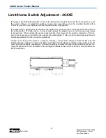
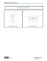
If equipped, the 404XE limit switches are set at the factory at the ends of travel and the home switch is set at
the center of travel. To adjust the switches, loosen the screw that secures the mounting bracket with a
2.5mm hex wrench, slide the switch into the desired position, and retighten.
If equipped with a sensor pack, the switches are adjusted by loosening the screw that secures the switch in
the channel with a #1 Phillips driver. To access these screws, the plastic top cover on the sensor pack needs
to be removed. When adjusting the sensor pack switches, the screws may be turned a maximum of 1/4 turn.
Any further loosening could result in the nut becoming disengaged. If this occurs the sensor pack will have to
be disassembled so that the nut can be reattached.
Printed on the body of the switch is a target (crosshairs). Limit switch settings to utilize full travel for the
404XE with long carriage (VL option) are 85mm and 75mm from the target centerline to the end block for the
motor and idler locations, respectively. Limit switch settings to utilize full travel for the 404XE with short car-
riage (NL option) are 51mm and 42mm from the target centerline to the end block for the motor and idler loca-
tions, respectively.
Limit/Home Switch Adjustment
-
404XE


