background image

Parker Hannifin Corporation


EMN Automation 

-

 Parker


Irwin, Pennsylvania


47


406LXR Series Product Manual 


Chapter 6 

-

 Maintenance and Lubrication


6. Remount carriage end caps. Insure that the  compression springs are present under the shoulder screws in 

the carriage end caps. Due to springs screws will need to be pressed into holes to start thread engagement.


Square Rail Bearing Lubrication


See previous section on 

Internal Access

 for access 

to interior of positioner.


Tools Requires:


Shell Alvania RL 2


Isopropyl Alcohol


Clean paper towels


Small brush


Lubrication Type:


Use Shell Alvania RL 2 pn# 003

-

3686

-

30, non

-

EP, lithium soap thickened greases. This grease 

also inhibited with additives that promote long 

service life and provide excellent lubrication and 

corrosion protection. Shell Alvania Grease RL 2 

is readily pumpable in pressure grease 

dispensing systems. 


Lubricant Appearance:


Smooth

-

textured, amber colored.


Maintenance Frequency:


Square rail bearing blocks are lubricated at our 

facility prior to shipment. For lubrication 

inspection and supply intervals following 

shipment, apply grease every 1000 hours of 

usage. The time period may change depending 

on frequency of use and environment. Inspect 

for contamination, chips, etc, and replenish 

according to inspection results.


Lubricant Application:


Wipe the rails down the entire length with a 

clean cloth. Apply lubrication on the rails 

allowing a film of fresh grease to pass under the 

wipers and into the recirculating bearings. 


After bearings are relubricated, clean encoder 

tape scale located on inside wall of table.  Use 

only isopropyl alcohol and a clean lint free cloth 

or paper towel. Using a lint free cloth, wipe 

down linear tape scale to remove and dirt or 

grease. 


Caution! 

DO NOT use and other solvent to 

clean the encoder scale. Use of other 

solvents will permanently damage the 

encoder scale. Use only isopropyl alcohol.


Note: Do not use/mix petroleum base grease with 

synthetic base grease at any time. For lubrication 

under special conditions consult factory.


Cable Management Module Replacement


Tools Requires:


Replacement Cable Management Module


Hex keys: 2.5mm and 2mm


Ball nose hex key: 3mm


Travel Code


Replacement 

Part Number


Travel Code


Replacement 

Part Number


Travel Code


Replacement 

Part Number


T01


006

-

2415

-

01


T06


006

-

2415

-

06


T11


006

-

2415

-

11


T02


006

-

2415

-

02


T07


006

-

2415

-

07


T12


006

-

2415

-

12


T03


006

-

2415

-

03


T08


006

-

2415

-

08


T13


006

-

2415

-

13


T04


006

-

2415

-

04


T09


006

-

2415

-

09


T14


006

-

2415

-

14


T05


006

-

2415

-

05


T10


006

-

2415

-

10


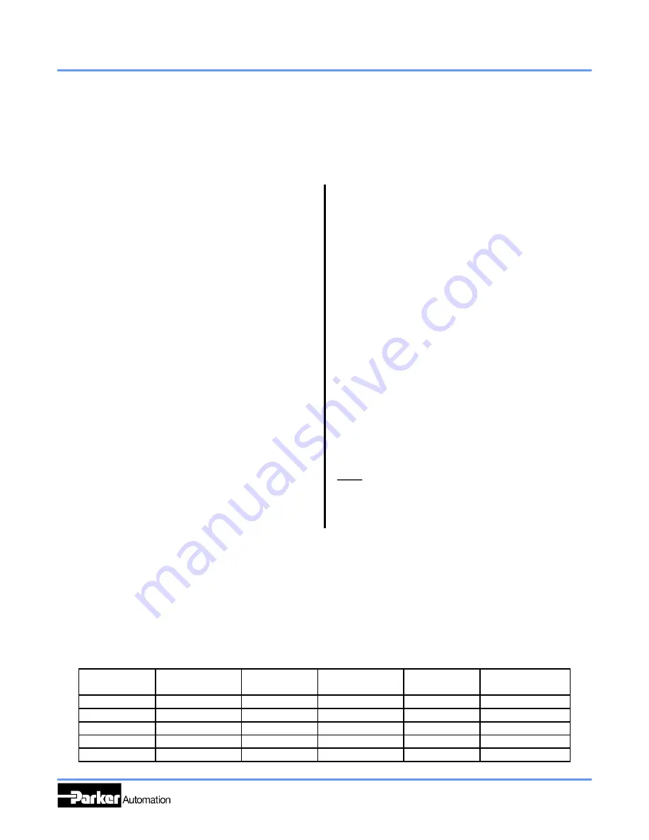
Replacement Cable Module Part Numbers


Summary of Contents for 406LXR Series

Page 1: ...Parker Manual No 100 5314 01 Rev H 406LXR Series Product Manual Effective June 6 2018 Supersedes December 20 2017 Electromechanical Positioning Systems Automation ...

Page 2: ...ce safety and warning requirements of the application are met The products described herein including without limitation product features specifications designs availability and pricing are subject to change by Parker Hannifin Corporation and its subsidiaries at any time without notice Important User Information The information in the product manual including any apparatus methods techniques and c...

Page 3: ...21 Mounting Surface Requirements 22 Side and Inverted Mounting 23 Setting Travel Limit Sensors 23 Setting Home Sensor 24 Z Channel Position Reference 24 Grounding Shielding 24 Cabling 25 CHAPTER 4 PERFORMANCE 27 Acceleration Limits 28 Speed Limits 29 Encoder Accuracy and Slope Correction 29 Thermal Effects on Accuraccy 31 Thermal Effects on Repeatability 32 Causes for Temperature Increases 32 Comp...

Page 4: ...ntenance section Revision 3 Updated Grease was Daedal Grease type 1 page 44 3 20 07 Revision 4 Added Aries and Compax3 OEM Cable option wiring diagrams Page 18 19 Updated Chapter 5 Connecting the Drive Amplifier to include the Compax3 option Revision 5 Clarified some warnings so it agrees with CE Risk assessment Page 2 Page 3 Revision 6 Re wrote step 5 on page 43 Revision G Removed all ribbon cabl...

Page 5: ...C H A P T E R O N E Introduction IN THIS CHAPTER Product Description 2 Unpacking 2 RMA Information 3 Warnings and Precautions 3 Specification Conditions 4 Assembly Diagrams 5 1 ...

Page 6: ...ng guidelines for handling and mounting of your new positioner Product may be heavy Standard handling and lifting practices should be employed DO NOT allow the positioner to drop onto the mounting surface Dropping the positioner can generate impact loads that may result in flat spots on bearing surfaces or misalignment of drive components DO NOT drill holes into the positioner Drilling holes into ...

Page 7: ...ents of the positioner while unit is plugged into an electrical outlet SHUT OFF power before replacing components to avoid electrical shock High Magnetic Field Unit may be HAZARDOUS to people with Pace Makers or any other magnetically sensitive medical devices Unit may have an effect on magnetically sensitive applications Ferrous Materials The positioner s protective seals MAY NOT keep out all sma...

Page 8: ... NO guarantee of any specification except motion of a standard unit before failure is 5 40 degrees C Specifications Are Mounting Surface Dependent Catalog specifications are obtained and measured when the positioner is fully supported bolted down and mounted to a work surface that has a maximum flatness error of 0 013mm 300mm 0 0005 ft Specifications Are Point of Measurement Dependent Catalog spec...

Page 9: ...on to all motorized configurations LINEAR MOTOR LINEAR ENCODER TAPE SCALE SQUARE RAIL BEARING MAGNET RAIL CABLE CARRIER CABLE CARRIER HOLD DOWN QUICK DISCONNECT CABLE ASSEMBLY CABLE CARRIER SUPPORT QTY VARIES BASED ON TRAVEL ADJUSTABLE LIMIT HOME TARGET 1 OF 3 PLUG IN CONNECTOR PANEL BUMPER ASSEMBLY 1 OF 4 AIR PURGE VACUUM PORT 1 PER END AIR FILTER 1 OF 2 ...

Page 10: ...rporation EMN Automation Parker Irwin Pennsylvania 6 406LXR Series Product Manual Chapter 1 Introduction Assembly Diagrams continued Strip seal components STRIP SEAL CLAMP 1 OF 4 STRIP SEAL 1 OF 2 CARRIAGE END CAP 1 OF 2 ...

Page 11: ...C H A P T E R T W O Table Specifications IN THIS CHAPTER Part Number Identification 8 Product Dimensions 9 Specification 10 Technical Data 12 Cable and Wiring Diagrams 17 Cleanroom Preparation 18 7 ...

Page 12: ...Parker Hannifin Corporation EMN Automation Parker Irwin Pennsylvania 8 406LXR Series Product Manual Chapter 2 Table Specifications Part Number Identification ...

Page 13: ...Parker Hannifin Corporation EMN Automation Parker Irwin Pennsylvania 9 406LXR Series Product Manual Chapter 2 Table Specifications 406LXR Series Dimension mm ...

Page 14: ...d Home Sensor Specifications Description Specification Input Power 5 VDC 5 150 mA Output Output form is factory set Normally Closed Current Sinking Normally Open Current Sinking Normally Closed Current Sourcing Normally Open Current Sourcing All types Sink or Source maximum of 50 mA Repeatability Limits 10 microns unidirectional Home See Z channel specifications Hall Effect Specifications Descript...

Page 15: ...e based on the peak to peak error measured by a laser interferometer and prism located at 50mm above the center of the table This type of measurement sums the X Y Z roll pitch and yaw errors Temperature deviations from test condition may cause deviations in straightness flatness accuracy and repeatability from catalog specifications Tests are performed with the table mounted to a granite table unl...

Page 16: ...oth static components resulting from payload weight and dynamic components due to acceleration deceleration of the load In multi axes applications the primary positioner at the bottom of the stack usually establishes the load limits for the combined axes When determining load life it is critical to include the weight of all positioning elements that contribute to the load supported by the primary ...

Page 17: ...Parker Hannifin Corporation EMN Automation Parker Irwin Pennsylvania 13 406LXR Series Product Manual Chapter 2 Table Specifications ...

Page 18: ...Parker Hannifin Corporation EMN Automation Parker Irwin Pennsylvania 14 406LXR Series Product Manual Chapter 2 Table Specifications ...

Page 19: ...B C D A B C D Gemini GV U6E Aries AR 04AE 120 VAC Input Gemini GV U6E Aries AR 04AE 240 VAC Input Commutation Chart 406 LXR Series Technical Data Force Speed Charts The charts on this page illustrate the characteristics of the 406LXR linear motor The force speed charts show the characteristics of the motor with either a 120 VAC or 240 VAC power input ...

Page 20: ...Parker Hannifin Corporation EMN Automation Parker Irwin Pennsylvania 16 406LXR Series Product Manual Chapter 2 Table Specifications ...

Page 21: ...Temp Yellow Orange 15 Ground Hall White Green Case Shield Green Yellow Limit Home 5 pin round connector Pin Number Function Wire color A 5 24 VDC Red B Neg Limit Blue C Pos Limit Orange D Home Green E Ground Black Case Shield Braid Shield Motor Power 6 pin round connector Pin Number Function Wire color 1 U Black 1 2 V Black 2 3 Ground Green Yellow 4 Reserved 5 Reserved 6 W Black 3 Case Shield Brai...

Page 22: ...LACK A WHITE A YELLOW B GREEN B BLUE Z ORANGE Z BROWN TEMP YELLOW ORANGE TEMP YELLOW ORANGE 5 HALL WHITE BLUE GROUND WHITE GREEN HALL 1 WHITE BROWN HALL 2 WHITE ORANGE HALL 3 WHITE VIOLET SHIELD GREEN YELLOW OEM Gemini Encoder Connector Function Cable Wire Color Pin 5 RED 1 GROUND BLACK 3 A WHITE 5 A YELLOW 6 B GREEN 7 B BLUE 8 Z ORANGE 9 Z BROWN 10 TEMP YELLOW ORANGE 12 TEMP YELLOW ORANGE 13 5 HA...

Page 23: ...ROWN 3 5 RED 4 TEMP YELLOW ORANGE 5 HALL 2 WHITE ORANGE 6 A YELLOW 7 A WHITE 8 HALL 3 WHITE VIOLET 9 TEMP YELLOW ORANGE 10 B BLUE 11 B GREEN 12 Z ORANGE 13 Z BLOWN 14 GROUND BLACK 15 SHIELD SHIELD SHIELD CASE OEM Gemini and Aries Limit and Home Connections Function Cable Wire Color Flying Leads 5 24 VDC RED LIMIT ORANGE LIMIT BLUE HOME GREEN GROUND BLACK SHIELD GREEN YELLOW OEM Compax3 Limit and H...

Page 24: ...ness of class 10 prior to testing Tables were tested in a variety of orientations with sampling both below the table and at the carriage mounting surface with a particle counter capable of measuring 0 3 m diameter and larger particles Based on results from testing following the 209E Federal Standard the following chart shows the expected cleanroom compatibility of the 406LXR with Class 10 cleanroo...

Page 25: ...C H A P T E R T H R E E Setup and Usage IN THIS CHAPTER Mounting Surface 20 Setting Limit Home sensors 21 Z Channel Marker 22 Cabling 23 21 ...

Page 26: ...ted to surfaces that do not meet the above conditions If the surface does not met these specifications the surface can be shimmed to comply with these requirements If mounting conditions require that the table base is overhung table specifications will not be met over that portion of the table Additionally in X Y Systems the overhung portion of the Y axis may not met specifications due to the addi...

Page 27: ...ation Rate must be known or calculated The maximum speed should be known from your application requirements Velocity limits should be set in your program or in your amplifier to cause a fault if the speed exceeds this value The maximum deceleration is a factor of load and available peak force of the table Using F ma calculate maximum acceleration and then required deceleration distance See the fol...

Page 28: ...inal home direction is to be toward the positive side of the table See Chapter 2 Dimensional Drawing for positive direction definition The repeatability of the Z channel is equal to 2 resolution counts of the encoder except for 0 1 µm scales which have a repeatability of 1 µm Thus the repeatability of the Z channel equals Encoder Resolution Z Channel Repeatability 5 µm 10 µm 1 µm 2 µm 0 5 µm 1 µm ...

Page 29: ... module removal and installation please see Chapter 6 Maintenance and Lubrication refer to the section Titled Cable Management Module Replacement Un harnessed OEM Cable System This option provides high flex round cables directly from the carriage This option is provided for applications where the design of the machine already has a cable management system Five cables come from the carriage connect...

Page 30: ...26 ...

Page 31: ...C H A P T E R F O U R Performance IN THIS CHAPTER Acceleration Limits 26 Speed Limits 27 Encoder Accuracy and Slope Correction 27 Thermal Effects on Accuracy and Repeatability 29 27 ...

Page 32: ...less loading is significantly cantilevered causing high moment loads during accelerations See Chapter 2 406LXR Series Technical Data to determine bearing load life for your application Available Motor Force This is the primary factor that reduces acceleration This is simply the amount of motor force available to produce acceleration The larger the inertial and or frictional load the lower the acce...

Page 33: ...pe Correction Encoder Accuracy The 406LXR Series makes use of an optical linear encoder for positional feedback This device consists of a readhead which is connected to the carriage and a steel tape scale which is mounted inside the base of the 406LXR The linearity of this scale is 3 microns per meter however the absolute accuracy can be many times larger To compensate for this error an error plot...

Page 34: ...240 Positions mm Error Microns Example Below is a sample program showing how to correct for slope error using variables This example program will work with the 6K as well as the 6000 Series Parker Controllers Step 2 through 3 of this program should be made a subroutine This subroutine can then be executed for each distance Step 1 VAR1 1280 IN THIS CASE THE DESIRED DISTANCE IS 1280mm Step 2 DEL SLC...

Page 35: ...r motion program This method provides excellent accuracy but is time consuming to setup Attainable Accuracy with Slope Correction Travel mm Accuracy µm Travel mm Accuracy µm 50 12 750 36 150 12 850 36 250 12 950 40 350 16 1200 48 450 24 1550 64 550 24 1750 72 650 28 1950 84 Thermal Effects on Accuracy All specifications for the 406LXR are taken at 20 C Variation from this temperature will cause ad...

Page 36: ...ffected as the temperature changes from one level to another This is most commonly experienced when starting an application cold Then as the application runs the 406LXR comes to its operational temperature The positions defined when the unit was cold will now be offset by the thermal expansion of the unit To compensate for this offset all positions should be defined after the system has been exerc...

Page 37: ...perature or program a thermal compensation factor into your motion program Controlling the base temperature is the best method However this means controlling the ambient temperature by removing all heat cold generators from the area and operating at very low duty cycles Compensation is the other way of achieving accuracy without sacrificing performance In this case the system must be exercised thr...

Page 38: ...34 ...

Page 39: ...C H A P T E R F I V E Connecting the Drive Amplifier IN THIS CHAPTER Drive Connections 34 Cables Adapters and Accessories 35 Limit Home Connections 36 35 ...

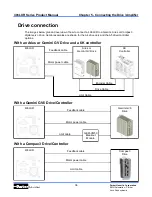
Page 40: ...verview of how to connect a 406LXR to a Gemini Aries or Compax3 digital servo drive Gemini examples are shown for the A4 drive only and the A5 drive controller options Drive Cable Encoder Cable Limit Cable Feedback cable 406LXR Aries or Gemini GV Drive Motor power cable 6K Controller Feedback cable 406LXR Gemini GV6 Drive Motor power cable Limit cable GEM VM50 Breakout Module With a Compax3 Drive ...

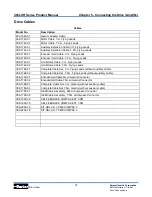
Page 41: ... Cable 3 m Flying Leads 006 1742 02 Limit Home Cable 7 5m Flying Leads 006 1788 01 Complete Cable Set 3 m Flying Leads without auxiliary cable 006 1788 02 Complete Cable Set 7 5m Flying Leads without auxiliary cable 006 1739 01 Encoder Hall Cable 3m w Gemini Connector 006 1739 02 Encoder Hall Cable 7 5m w Gemini Connector 006 1789 01 Complete Cable Set 3 m Gemini without auxiliary cable 006 1789 0...

Page 42: ... 10 10 cable RS 232 485 null modem CE LVD EMC 71 016943 10 10 cable 50 pin high density Amp Champ 71 016945 03 3 cable 50 pin high density Amp Champ 71 016966 10 Gemini to 6K Step Direction command cable 10 71 016987 10 Gemini to 6K Analog command cable 10 CE GC 26 Gemini Feedback Connector with 26 pin terminal strip GC 50 Gemini I O Connector with 50 pin terminal strip GEM VM50 Kit consisting of ...

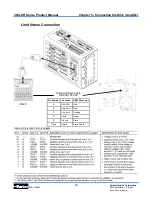
Page 43: ... 406LXR Series Product Manual Chapter 5 Connecting the Drive Amplifier LXR Limit Home Cable P N 006 1742 0X Pin Number Function OEM Wire color A 5 24 VDC Red B Neg Limit Blue C Pos Limit Orange D Home Green E Ground Black Case Shield Braid Shield Limit Home Connection VM25 ...

Page 44: ...IS CHAPTER Product Version Identification 38 Internal Access Procedure 39 Square Rail Bearing Lubrication 44 Cable Module Removal and Replacement 44 Cable Carrier Support Adjustment 47 Limit Home Module Replacement 48 Filter Cleaning and Replacement 50 40 ...

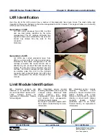
Page 45: ...at head socket cap screws thru the top of the connector near the carriage G2 cable management also features an auxiliary pass thru port on the carriage connector and connector panel G2 LXR s and cable management are shown throughout this manual Limit Module Identification G1 Limit Module G2 Limit Module G3 Limit Module G1 Individual sensors are attached to an aluminum angle G1 limits are ONLY usab...

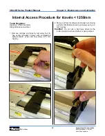
Page 46: ... shoulder screws with compression spring preload 2 per end cap using a 2 5 mm hex key Internal Access Procedure for travels 1250mm 2 Remove all four 4 strip seals clamps by removing eight 8 M3 Button Head Cap Screws using a 2 mm hex key Caution Do not use a ball nose driver as the button head screw hex interface is easily striped Tools Requires Hex keys 2 5mm and 2mm Straight blade screw driver ...

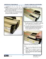
Page 47: ...tment is completed install the strip seal clamps 4pc Fully tighten the outside bolts 4pcs Not the bolts going through the cover Next snug each of the four bolts going through the cover until movement through the cover until movement between the cover and the carriage can be seen At this point stop tightening the screw is adjusted correctly Repeat this to the other 3 screws 4 Pull both strip seals ...

Page 48: ...ws using a 2 mm hex key Caution Do not use a ball nose driver as the button head screw hex interface is easily striped 1 Remove carriage end caps by removing four 4 hex socket shoulder screws with compression spring preload 2 per end cap using a 2 5 mm hex key 2 Measure gap between top crown of center cover and bottom of carriage when carriage is at center of travel Write down this measurement You...

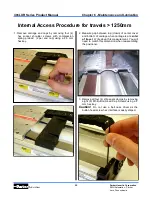
Page 49: ...finger nail Note Later version LXR s may have thicker clamping bars without locating pins Thicker clamping bars can be retro fitted to older LXR s by simple removing the locating pins with pliers 7 Pull center cover through carriage 5 Pull both strip seals through carriage Caution The strip seal ends are VERY SHARP 6 Remove four 4 M3 Adjustment Button Head Cap Screws from counter bored holes in ce...

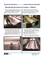
Page 50: ... into the center cover using a 2 mm Hex key Note Do not tighten screws at this point 2 Feed the strip seals back through the carriage Strip seals and Adjustment Button Head Cap Screws will be very close in proximity to one another Make sure Adjustment Button Head Cap Screws will NOT pinch strip seals when tightened down Place strip seals over locator pins Caution The strip seal ends are VERY SHARP...

Page 51: ...equency of use and environment Inspect for contamination chips etc and replenish according to inspection results Lubricant Application Wipe the rails down the entire length with a clean cloth Apply lubrication on the rails allowing a film of fresh grease to pass under the wipers and into the recirculating bearings After bearings are relubricated clean encoder tape scale located on inside wall of t...

Page 52: ...ove the two 2 screws found inside the connector hosing 3 Loosen the M4 button head screw using a 2 5mm hex key Slide the cable carrier hold clamp off of the cable carrier support Mark or take careful note of which cable support the hold down is attached to for reinstallation 4 Using a 2mm hex key Remove the two 2 flat head screw on the top of the carriage connector module Caution Do not use a ball...

Page 53: ...l the carriage connector straight away from the carriage Then lift the cable carrier up out of the cable carrier supports 1 With the carriage moved to the end of travel on the connector panel end Place the cable carrier into the carrier supports with the connector panel slid off the end of the table 2 Slide the carriage connector straight onto the carriage using the mounting holes as an alignment ...

Page 54: ...d so the lower screw hole is away from the table 6 Reinstall the cable carrier hold down on the same support it was removed from Typically no adjustment of the cable carrier supports is needed However If the support becomes lose or a slight movement of the support is needed for clearance or access to associated equipment the support can be moved easily Even spacing of the carrier supports is requi...

Page 55: ... be quite robust and withstand most out of specification conditions such as over voltage reverse polarity and short circuiting However some extreme condition can cause the failure of the module Is such a case the module is easily replaceable in the field Please contact your local distributor or Parker Hannifin for replacement part number information Tools Requires Hex keys 2mm 1 5mm T6 Torx or Tor...

Page 56: ...ment screws Very little torque is needed to attach hosing 2 Connect cable module wiring to limit module Check that connection is secure G2 Latch should click in place G3 Connector should be fully engaged and flush with connector housing Note If replacing a G2 module with a G3 unit an adapter cable is required and should have been included with your replacement limit home module Please contact fact...

Page 57: ...dia retain and press the retainer into the body until it snaps into place Reassembly 4 Using four 4 button head screws per end attach the filter assembly to the end block Filter Cleaning and Replacement During operation air is drawn into the body of the LXR thru the vents located on each end of the base The movement of the carriage pulls air in and out of the body cavity in considerable volume The...

Page 58: ...ices IN THIS SECTION Understanding Linear Motors 52 Linear Motor Benefits 52 Slotless Linear Motor Design 52 Advantages Disadvantages of Slotless Linear Motors 53 IP Ratings 54 Warning 54 IP Preparation 55 54 ...

Page 59: ...e there is no mechanical linkage in a linear motor increasing the stiffness is simply a matter of gain and current Thus the spring rate of a linear motor driven system can be many times that of a ball screw driven device However it must be noted that this is limited by the motor s peak force the current available and the resolution of the feedback Zero Backlash Since there are no mechanical compon...

Page 60: ...us reducing the possibility of motor fatigue failures Light Weight Forcer Because of its aluminum body construction the slotless linear motor forcer weight is approximately 2 3 that of an equivalent iron core linear motor Thus resulting in higher throughput in light load applications Lower Attractive Forces The slotless design has a backiron causing attractive forces between the forcer and the rai...

Page 61: ...protection of equipment against solid foreign objects of 12 5 mm diameter and larger 3 Protection against access to hazardous parts with a tool and protection against solid foreign objects of 2 5 mm diameter and larger Second Number The second number indicates protection of internal equipment against harmful ingress of water 0 No special protection provided Note Number Indicators above represent o...

Page 62: ...ll unused carriage mounting holes that are not covered by the load or load plate Note Only insert the set screws until they are flush or slightly recessed from the mounting surface If they are inserted too deeply they will make contact with the extrusion or center cover and may cause failure 3 Using the supplied M6 set screws plug all threaded base mounting holes that are not covered by your mount...

Page 63: ...6 Version Identification 41 Load Rating 10 Load life chart 12 Bearing 12 Normal loading 13 Side loading 13 Calculation 14 Lubrication 47 Maintenance Bearing Lubrication 47 Cable Module 47 Cable Carrier Support 47 Filter 53 Internal Access 42 46 Limit Home Module 51 Mass 10 Moment 12 14 Motor Advantages 56 Design 55 Force 10 Motor Heating 33 Mounting Surface Requirements 22 Methods 22 Side Inverted...

Page 64: ...Parker Hannifin Corporation EMN Automation Parker Irwin Pennsylvania Notes ...

Page 65: ...Parker Hannifin Corporation EMN Automation Parker Irwin Pennsylvania Notes ...

Page 66: ...Parker Hannifin Corporation EMN Automation Parker Irwin Pennsylvania Notes ...

Page 67: ...Parker Hannifin Corporation EMN Automation Parker Irwin Pennsylvania Notes ...

Page 68: ......

Reviews: