background image

Bulletin MSG30-3245-INST/UK 

Installation Manual

4

Parker Hannifin

Pump & Motor Division Europe

Chemnitz, Germany

Axial Piston Pump

Series PV, series 44 and higher

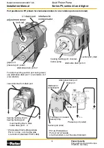
interface for 

compensator

alternative drain port L2

L1 drain port

pressure port (outlet)

gage port

adjustment screw
 

lock nut

Port positions for PV (shown for clockwise rotation, for ccw rotation ports are mirrored)

suction port (inlet)

bearing flushing port, covered, 

below pump

alternative drain port L3

case drain line from drain port

main flushing line to alter-

native drain port 1, 2

bearing flushing line to 

bearing flushing port

*  PV016-092+PV270-PV360 DS45  

Port L1 on top ; L2,L3 at the side  

L4 at bottom (standard: PV270-360)

Interface for 

compensator

Alternative drain port

Drain port

Pressure port (outlet)

Suction port (inlet)

Gage port

Flushing port, covered 

below pump

*   PV140-PV180-KS44   

Ports L1/L2 at topside,  

L3 at the bottom, L4 at the side (Standard)

For side mounting (suction port facing down) 

use alternative drain port 1 (cw rotation) or 2 

(ccw rotation).

Summary of Contents for 44 Series

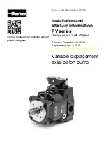
Page 1: ...additional support parker com pmde Effective December 20 2018 Supersedes July 1 2010 Bulletin MSG30 3245 INST UK Installation and start up information PV series Design series 44 PVplus Variable displacement axial piston pump ...

Page 2: ...making the final selection of the products and systems and assuring that all performance and safety requirements of the application are met The products are subject to change by Parker Hannifin GmbH at any time without notice Contents Page 1 Installation and start up 3 2 Displacement adjustment 6 3 Standard pressure compensator code MMC 6 4 Standard pressure compensator with D03 interface code MM1...

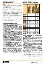
Page 3: ...low pressure pipe avoid sharp el bows and any restriction of cross section The suction pipe must have access to clean cooled and filtered fluid free of air bubbles No tur bulences or high flow velocities should occur at the tube inlet Therefore position inlet as far as possible away from return line and drain line Make sure that the fluid circulation in the reservoir does keep return flow from suc...

Page 4: ...hing port covered below pump alternative drain port L3 case drain line from drain port main flushing line to alter native drain port 1 2 bearing flushing line to bearing flushing port PV016 092 PV270 PV360 DS45 Port L1 on top L2 L3 at the side L4 at bottom standard PV270 360 Interface for compensator Alternative drain port Drain port Pressure port outlet Suction port inlet Gage port Flushing port ...

Page 5: ...mandatory to avoid noise and vibration being induced into the frame work The reservoir needs to be carefully sealed against ingression of contamination and water A level indica tor and thermometer should be placed in an easily accessible location Fluid content general rule stationary systems 3 to 4 times pump nominal flow 1 times or even smaller in mobile systems Filling of the system Use only hig...

Page 6: ...ing the adjustment screw clockwise will reduce the pumps displacement For the sizes PV016 PV092 the thread pitch is 1mm for sizes PV140 PV360 the thread pitch is 1 5 mm The table shows the displacement change per mm resp per turn and the minimum adjustable displacement Note All pumps are adjusted and tested after as sembly in our factory Only the compensator pressure needs to be adjusted That is d...

Page 7: ...NG6 DIN 24 340 compensator differential adjustment lock nut pressure adjustment lock nut 5 Standard pressure compensator for accessory mounting code MMZ interface NG6 DIN 24 340 Version MMZ is designed especially for compen sator accessory mounting ordering code PVAC see chapter 12 Because the accessory packages come with their own pilot valves this version has no integrated pilot catridge to avoi...

Page 8: ...g or flow compensator primarily controls the pump output flow To achieve this the load pressure after a main stream throttle valve load sensing valve not included in the shipment of the pump is connected to the load sensing port of the compensator The compensator control strategy is to keep the pressure drop constant across this main stream throttle valve The integrated pilot valve maintains a pre...

Page 9: ... two spool compensator code MT has two separate compensator valves for flow load sensing and pressure compensation That results in a steeper pressure compensation curve which can be beneficial in certain applications The flow control stage has no integrated pilot valve because this would eliminate the effect of the two spool control The pressure stage has no integrated pilot valve because during f...

Page 10: ...e power compensator with load sensing code C a modified load sensing compensator is used Constant horse power curve with adjustment 9 Horse power compensator codes L C Adjustment A tolerance compensation for optimized performance done at pilot cartridge Adjustment B maximum pressure setting done at integrated pressure pilot valve At the adjustment screw of the horse power pilot valve a basic adjus...

Page 11: ...ing and stand by pressure In neutral position both cartridges are con nected to the compensator valve The lower pressure defines the compensating pressure of the pump When the A solenoid B side of the DCV is energized only the A side cartridge is connected the higher pressure adjusted there defines the compensating pressure When solenoid B is energized the valve spool con nects all four ports Then...

Page 12: ...blocked E g by plugs cleaning tissues plastic plugs Ball valve in the suction line closed Suction filter blocked Solution Check suction line for free flow Open valves in suction line Valves should be equipped with electrical indicator Check suction filter Reason Suction line not gas tight pump gets air into suction port Solution Seal suction line against air ingression Reason Pressure line system ...

Page 13: ...r side of load sensing valve Reason No or too low pressure at pump outlet port Solution Pump outlet pressure must be at least 15 bar because otherwise the bias spring in the pump cannot be compressed Pump does not upstroke sticks at zero displacement Reason Compensator is blocked due to contamination Solution Clean hydraulic fluid clean compensator valve Reason Cable to LVDT or proportional soleno...

Page 14: ...Bulletin MSG30 3245 INST UK Installation Manual 14 Parker Hannifin Pump Motor Division Europe Chemnitz Germany Axial Piston Pump Series PV series 44 and higher Notes ...

Page 15: ...PRODUCTS DESCRIBED HEREIN OR RELATED ITEMS CAN CAUSE DEATH PERSONAL INJURY AND PROPERTY DAMAGE This document and other information from Parker Hannifin Corporation its subsidiaries and author ized distributors provide product or system options for further investigation by users having technical expertise The user through its own analysis and testing is solely responsible for making the final selec...

Page 16: ...rope Chemnitz Germany Axial Piston Pump Series PV series 44 and higher Parker Hannifin MSG30 3245 INST UK Manufacturing Germany GmbH Co KG Pump Motor Division Europe Neefestr 96 D 09116 Chemnitz Tel 49 0 371 3937 0 Fax 49 0 371 3937 488 Copyright 2018 www parker com pmde All rights reserved ...

Reviews: