background image

Bulletin MSG30-3245-INST/UK

Installation and  

start-up information 

Variable displacement 

axial piston pump  

PV series

Design series ≥

 47

, PV

plus

Effective: November, 2021

Supersedes: December, 2018

Visit our homepage 

for additional support

parker.com/pmde

Summary of Contents for 47 Series

Page 1: ...ST UK Installation and start up information Variable displacement axial piston pump PV series Design series 47 PVplus Effective November 2021 Supersedes December 2018 Visit our homepage for additional support parker com pmde ...

Page 2: ...responsible for making the final selection of the products and systems and assuring that all performance and safety requirements of the application are met The products are subject to change by Parker Hannifin GmbH at any time without notice Contents Page 1 Installation and start up 3 2 Displacement adjustment 6 3 Standard pressure compensator code MMC 6 4 Standard pressure compensator with D03 in...

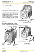
Page 3: ...from bottom 2 3 times diameter and even at lowest fluid level approx 200 mm below fluid level Inlet pres sure even during compensation never should drop below 0 8 bar absolute Absolute gas tight connection risk of cavitation noise Air bubbles due to vacuum in the inlet can destroy pumps within a short time due to cavitation erosion Suction pipe should be as short as possible Use only clean low pre...

Page 4: ...ide mounting suction port facing down use alternative drain port 1 cw rotation or 2 ccw rotation Note During operation of PV pumps of all sizes under the following conditions Q Qmax pinlet 2 bar absolute Poutlet 25 bar e g low pressure circulation the drain flow can change direction Fluid is taken from the case into the piston mainly through the decompression orifice and across the slippers There ...

Page 5: ...ow Drive input For direct drive use elastic coupling free of axial and radial reaction forces Please follow strictly theinstructionsofthecouplingsupplierregarding axial clearance axial displacement and angular tolerances Couplings never shall be mounted using a hammer Threads in the shaft end allow smooth mounting of the coupling The drive shaft should only carry true torque Contact Parker for all...

Page 6: ...d or bypass filtration Bypass filtration usually is most efficient For general purpose hydraulic systems with limited requirements for operational life contamination level 19 15 according to ISO 4406 should be desired corresponding filter rating x 25 µm b25 75 according to ISO 4572 Cleanliness level for systems with higher re quirements for operational life and functional safety should be 18 16 13...

Page 7: ...t approx cm U PV016 1 5 1 5 9 PV020 1 5 1 5 13 PV023 1 5 1 5 16 PV028 1 5 1 5 20 PV032 2 2 2 2 17 PV040 2 2 2 2 25 PV046 2 2 2 2 30 PV063 3 4 5 1 35 PV080 3 4 5 1 50 PV092 3 4 5 1 65 PV140 5 6 8 4 20 PV180 5 6 8 4 60 PV270 6 8 10 2 120 PV360 8 6 12 9 180 pressure compensator can be made remote controllable This adapter replaces one of the side plugs Adapters are available for G1 4 M14x1 5 ISO 6149...

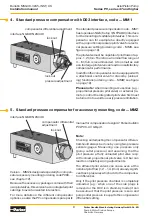
Page 8: ...ompensator differential adjustment lock nut pressure adjustment lock nut 5 Standardpressurecompensatorforaccessorymounting code MMZ interface NG6 DIN 24 340 Version MMZisdesignedespeciallyforcompen satoraccessorymounting orderingcodePVAC see chapter 12 Because the accessory packages come with their ownpilotvalves thisversionhasnointegratedpilot catridge to avoid unwanted interaction For more detai...

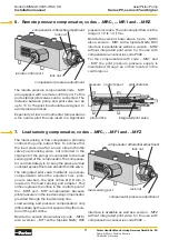
Page 9: ... across this main stream throttle valve The integrated pilot valve maintains a pressure compensation when the adjusted max pres sure is reached The pilot orifice Ø 0 8 mm is located in the load sensing port adapter This orifice replaces the orifice in the control spool of the MM and MR compensators because pilot pressure is in the load sensing compensator provided through the load sensing line Loa...

Page 10: ... D1VW002K JW for stand by operation 24 VDC normally open Compensator code MMK with proportional pressure pilto valve code PVACRES K35 8 Two spool load sensing compensator codes MTP and MTK interface NG6 DIN24 340 for pilot valve pressure control stage load sensing port flow control stage The two spool compensator code MT has two separate compensator valves for flow load sensing and pressure compen...

Page 11: ...sated pumps dif fer from standard compensator valves only in the fact that a plug in a connecting hole is removed For a standard horse power compensator with ordering code L a modified remote pressure compensatorisused Forahorsepowercompen sator with load sensing code C a modified load sensing compensator is used 9 Horse power compensator codes L C pensator is 15 1 bar These adjustments should not...

Page 12: ...s codes PVAC2P PVAC2E and PVAC2M a sandwich valve with twodirect actionpressurecartridgevalvesisused to pilot the pump Adjustment A tolerance compensation for opti mized performance done at pilot cartridge Adjustment B maximum pressure setting done at integrated pressure pilot valve Constant horse power curve with adjustment At the adjustment screw of the horse power pilot valve a basic adjustment...

Page 13: ...pump the pump compensates at minimum compensating pressure stand by The directional control valve series D1VW has spool code 055 This spool code is used to avoid a blocked spool position during transient This version is recommended when during a machine cycle the pressure is to be switched between high and low For code PVAC2M also a dual solenoid valve is used In neutral position all four ports ar...

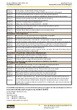
Page 14: ...Suction line is blocked E g by plugs cleaning tissues plastic plugs Ball valve in the suction line closed Suction filter blocked Solution Check suction line for free flow Open valves in suction line Valves should be equipped with electrical indicator Check suction filter Reason Suction line not gas tight pump gets air into suction port Solution Seal suction line against air ingression Reason Press...

Page 15: ...ilot valve connected to compensator or valve is blocked Solution Connect pressure pilot valve to compensator make sure valve opens as required Reason Load sensing line connected incorrectly e g upstream of load sensing valve Solution Connect load sensing line downstream actuator side of load sensing valve Reason No or too low pressure at pump outlet port Solution Pump outlet pressure must be at le...

Page 16: ...at such data and specifications are suitable and sufficient for all applications and reasonably foreseeable uses of the components or systems Offer of Sale Please contact your Parker representation for a detailed Offer of Sale WARNING USER RESPONSIBILITY Position notification regarding Machinery Directive 2006 42 EC Products made by the Pump Motor Division Europe PMDE of Parker Hannifin are exclud...

Reviews: