3-46
Installing the Drive
DC590+ DRV Series DC Digital Drive
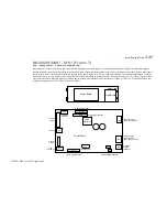
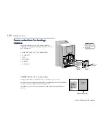
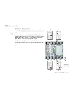
Feedback Receiver Board Installation
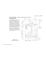
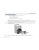
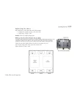
Each speed feedback board mounts on the lower left portion of the control board as shown above. Terminal assignments for each option board are
listed in Appendix E and in the documentation shipped with the boards.
To install the receiver board on the drive control board:
1. Remove the packaging from the feedback receiver board.
Caution
Caution
Encoder and Microtach receiver boards contain electrostatic discharge (ESD) sensitive parts. Observe static control precautions when
handling and installing the board.
2. Align the 10-pin connector on the option board with the controller pins on the lower left of the control board.
3. Carefully push the receiver board onto the pins taking care not to bend the pins. All four white support standoffs should engage the control board. If
installing a switchable analog tachometer generator calibration board, be sure to connect the jumper on the right side of the board to its mating jack.
4. Refer to the Technical Manual supplied with the Option for specific instructions.
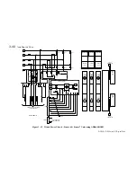
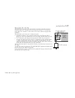
Analog Tachometer Generators (G1, G2, G3, G4)
The switchable tachometer calibration board option supports both AC and DC analog tachometer
generators with a calibration range of 10 to 209 volts. The calibration resistors and the board switch
settings coarsely scale the speed feedback signal. Adjust parameters in the MMI for fine-tuning (refer to
Chapter 4).
The signal cable for the analog tachometer generator
must
be shielded over its entire length.
NOTE
Ground the tachometer generator shield at the drive end only to avoid ground loops.
Terminals G1 & G2 are for AC tacho connections.
Terminals G3 & G4 are for DC tacho connections.
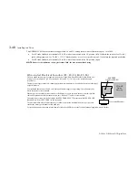
The speed loop is set-up for an analog tacho by the SPEED FBK SELECT parameter in the SPEED LOOP
function block. Select ANALOG TACH for this parameter.
NOTE
If an AC tachogenerator is used, the output is rectified to produce the dc feedback to the speed loop.
Consequently, the drive can only be used with a positive setpoint.
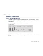
Analog Tachogenerator
TACHO CALIBRATIO N
O PTIO N BO ARD
CO MM S
Option
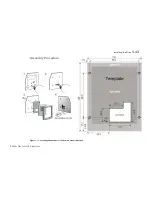
M ounting
Summary of Contents for 590+ DRV
Page 1: ...590 DRV Frame 1 2 3 4 5 6 7 HA470388U003 Issue 2 Product Manual...
Page 2: ......
Page 14: ......
Page 16: ...DC590 DRV DC Digital Drive...
Page 20: ...DC590 DRV Series DC Digital Drive...
Page 38: ...DC590 DRV Series DC Digital Drive...
Page 126: ...3 88 Installing the Drive DC590 DRV Series DC Digital Drive...
Page 128: ...DC590 DRV Series DC Digital Drive...
Page 158: ...DC590 DRV Series DC Digital Drive...
Page 166: ...5 8 Control Loops DC590 DRV Series DC Digital Drive...
Page 168: ...DC590 DRV Series DC Digital Drive...
Page 194: ...DC590 DRV Series DC Digital Drive...
Page 226: ...DC590 DRV Series DC Digital Drive...
Page 244: ...DC590 DRV Series DC Digital Drive...
Page 274: ...A 30 Serial Communications DC590 DRV Series DC Digital Drive...
Page 276: ...DC590 DRV Series DC Digital Drive...
Page 292: ...B 16 Certification DC590 DRV Series DC Digital Drive...
Page 294: ...DC590 DRV Series DC Digital Drive...
Page 330: ...C 36 Parameter Specification Tables DC590 DRV Series DC Digital Drive...
Page 348: ......
Page 368: ...D 20 Programming DC590 DRV Series DC Digital Drive Functional Description...
Page 496: ...D 148 Programming DC590 DRV Series DC Digital Drive Programming Block Diagram Sheet 1...
Page 497: ...Programming D 149 DC590 DRV Series DC Digital Drive Programming Block Diagram Sheet 2...
Page 498: ...D 150 Programming DC590 DRV Series DC Digital Drive Programming Block Diagram Sheet 3...
Page 499: ...Programming D 151 DC590 DRV Series DC Digital Drive Programming Block Diagram Sheet 4...
Page 504: ...D 156 Programming DC590 DRV Series DC Digital Drive...
Page 506: ...DC590 DRV Series DC Digital Drive...
Page 543: ......


