590 Series DC Digital Drive
Trips and Fault Finding
7-3
Trips and Fault Finding
Trips
What Happens when a Trip Occurs
When a trip occurs, the Drive’s power stage is immediately disabled causing the motor and load to coast to a stop. The trip is latched until action is
taken to reset it. This ensures that trips due to transient conditions are captured and the Drive is disabled, even when the original cause of the trip is no
longer present.
Drive Indications
If a trip condition is detected the unit displays and performs the following actions.
1.
The HEALTH LED goes out indicating a Trip condition has occurred. (Investigate, find and remove the cause of the trip.)
2.
Terminal B6 (Healthy) goes low (0V).
3.
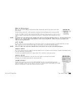
The MMI displays the activated alarm.
4.
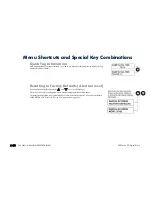
The alarm message(s) can be acknowledged by pressing the
E
key, however, the unit will not restart at this point.
Resetting a Trip Condition
All trips must be reset before the Drive can be re-enabled. A trip can only be reset once the trip condition is no longer active, i.e. a trip due to a
heatsink over-temperature will not reset until the temperature is below the trip level.
NOTE
More than one trip can be active at any time. For example, it is possible for both the HEATSINK TRIP and the OVERVOLTS (VA) trips to
be active. Alternatively it is possible for the Drive to trip due to a FIELD OVER I error and then for the HEATSINK TRIP trip to become
active after the Drive has stopped (this may occur due to the thermal time constant of the heatsink).
You can reset the trip(s) in one of two ways:
1.
Power-up, or remove and re-apply the auxiliary power supply.
2.
Stop and start the drive, i.e. remove and re-apply the Start/Run signal (terminal C3 or C4, or the STOP and RUN keys on the MMI).
Success is indicated by the HEALTH LED (on the unit ) illuminating. The MMI will return to its original display.
Summary of Contents for 590C
Page 1: ...DC590 series Digital Drive HA467078U001 Issue 2 Product Manual...
Page 2: ...Cont 2...
Page 13: ...Cont 12...
Page 15: ...1 2 Getting Started 590 Series DC Digital Drive...
Page 19: ...2 2 Product Overview 590 Series DC Digital Drive...
Page 25: ...2 8 Product Overview 590 Series DC Digital Drive...
Page 27: ...3 2 Installing the Drive 590 Series DC Digital Drive...
Page 66: ...590 Series DC Digital Drive Installing the Drive 3 41 Figure 3 11 110A 150A Stack Assembly...
Page 67: ...3 42 Installing the Drive 590 Series DC Digital Drive Figure 3 12 180A Stack Assembly...
Page 68: ...590 Series DC Digital Drive Installing the Drive 3 43 Figure 3 13 270A Stack Assembly...
Page 83: ...3 58 Installing the Drive 590 Series DC Digital Drive...
Page 85: ...4 2 Operating the Drive 590 Series DC Digital Drive...
Page 113: ...4 30 Operating the Drive 590 Series DC Digital Drive...
Page 115: ...5 2 Control Loops 590 Series DC Digital Drive...
Page 123: ...6 2 The MAN MACHINE INTERFACE MMI 590 Series DC Digital Drive...
Page 129: ...6 8 The MAN MACHINE INTERFACE MMI 590 Series DC Digital Drive The Menu System Map...
Page 145: ...7 2 Trips and Fault Finding 590 Series DC Digital Drive...
Page 157: ...7 14 Trips and Fault Finding 590 Series DC Digital Drive...
Page 159: ...8 2 Routine Maintenance and Repair 590 Series DC Digital Drive...
Page 165: ...A 2 Serial Communications 590 Series DC Digital Drive...
Page 197: ...B 2 Certification 590 Series DC Digital Drive...
Page 211: ...B 16 Certification 590 Series DC Digital Drive...
Page 213: ...C 2 Parameter Specification Tables 590 Series DC Digital Drive...
Page 373: ...D 124 Programming 590 Series DC Digital Drive Programming Block Diagram Sheet 1...
Page 374: ...590 Series DC Digital Drive Programming D 125 Programming Block Diagram Sheet 2...
Page 375: ...D 126 Programming 590 Series DC Digital Drive Programming Block Diagram Sheet 3...
Page 381: ...E 2 Technical Specifications 590 Series DC Digital Drive...


