E-20
Technical Specifications
590 Series DC Digital Drive
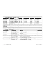
Terminal Information – Control Board
This Control Board is common to all 590 units.
Terminal Description
Terminal Function
Signal Level
Configurable Terminal
Number
+24V Supply +24V
Maximum output current: 250mA
Short circuit protected.
Up to 750mA only with AH385851 power board,
and only if LINK 24 is applied (shorting VP25 to
VP26, located above SW4 – 6 in the control
terminal area).
Applying LINK 24 disables short circuit protection.
Some typical loads are given below:
Microtach : 75mA
Relays : 50mA each
Fibre Optic ancillaries : 50mA each
N/A C9
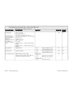
Terminal Information (Option Boards)
Terminal Description
Terminal Function
Signal Level
Terminal Number
TERMINAL BLOCK G (SWITCHABLE TACHO CALIBRATION OPTION)
+ AC Tacho input
+AC
G1
- AC Tacho input
- AC
G2
+ DC Tacho input
+DC
G3
- DC Tacho input
- DC
G4
(5701 MICROTACH RECEIVE OPTION - PLASTIC)
Signal Input
Microtach fibre optic
input
There are no other connections to this option module. (The 5701 Microtach should be
powered by an external 24V DC at 60mA, 1.4W.)
F1
Summary of Contents for 590C
Page 1: ...DC590 series Digital Drive HA467078U001 Issue 2 Product Manual...
Page 2: ...Cont 2...
Page 13: ...Cont 12...
Page 15: ...1 2 Getting Started 590 Series DC Digital Drive...
Page 19: ...2 2 Product Overview 590 Series DC Digital Drive...
Page 25: ...2 8 Product Overview 590 Series DC Digital Drive...
Page 27: ...3 2 Installing the Drive 590 Series DC Digital Drive...
Page 66: ...590 Series DC Digital Drive Installing the Drive 3 41 Figure 3 11 110A 150A Stack Assembly...
Page 67: ...3 42 Installing the Drive 590 Series DC Digital Drive Figure 3 12 180A Stack Assembly...
Page 68: ...590 Series DC Digital Drive Installing the Drive 3 43 Figure 3 13 270A Stack Assembly...
Page 83: ...3 58 Installing the Drive 590 Series DC Digital Drive...
Page 85: ...4 2 Operating the Drive 590 Series DC Digital Drive...
Page 113: ...4 30 Operating the Drive 590 Series DC Digital Drive...
Page 115: ...5 2 Control Loops 590 Series DC Digital Drive...
Page 123: ...6 2 The MAN MACHINE INTERFACE MMI 590 Series DC Digital Drive...
Page 129: ...6 8 The MAN MACHINE INTERFACE MMI 590 Series DC Digital Drive The Menu System Map...
Page 145: ...7 2 Trips and Fault Finding 590 Series DC Digital Drive...
Page 157: ...7 14 Trips and Fault Finding 590 Series DC Digital Drive...
Page 159: ...8 2 Routine Maintenance and Repair 590 Series DC Digital Drive...
Page 165: ...A 2 Serial Communications 590 Series DC Digital Drive...
Page 197: ...B 2 Certification 590 Series DC Digital Drive...
Page 211: ...B 16 Certification 590 Series DC Digital Drive...
Page 213: ...C 2 Parameter Specification Tables 590 Series DC Digital Drive...
Page 373: ...D 124 Programming 590 Series DC Digital Drive Programming Block Diagram Sheet 1...
Page 374: ...590 Series DC Digital Drive Programming D 125 Programming Block Diagram Sheet 2...
Page 375: ...D 126 Programming 590 Series DC Digital Drive Programming Block Diagram Sheet 3...
Page 381: ...E 2 Technical Specifications 590 Series DC Digital Drive...


