5
Electrical Installation
Electrical Installation
Electrical Installation
Electrical Installation
07-02-12-02-EN-V1215.doc / Type:
638
65
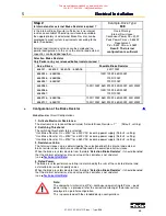
Step 2
Is internal and/or external Brake Resistor required ?
Example-Drive Type:
638
Is the internal Brake Resistor sufficient or is no internal
resistance available? Should no resistance be available
then appropriately sized external Brake Resistor can be
employed to meet system requirements according to the
table (See below),
External and internal resistance can be employed in a
parallel configuration. In this case the internal and external
capacities can be added together.
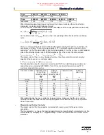
Overall Rating:
Internal Resistance:
Continuous Power Pd = 20W
Peak Power Pmax = 0,83kW
Requirement:
Pd = 9,3W Pmax = 405W
Result: The internal
configuration is sufficient
Selection Brake Resistor
Only Parker or by our released ballast resistors used !
Servo Drives
Possible Brake Resistor
638A01.. / 638A02.. / 638A04.. / 638A06..
33R 100W
638B033.. / 638B053..
638B036.. / 638B056..
638B037.. / 638B057..
100R 100W, 56R 200W
100R 100W
100R 100W
638B083..
638B086..
638B087..
100R 100W, 56R 200W, 36R 300W, 33R 300W
100R 100W, 56R 200W
100R 100W
638B106.. / 638B156..
638B107.. / 638B157..
100R 100W, 56R 200W, 36R 300W, 33R 300W
100R 100W, 56R 200W, 36R 300W, 33R 300W
●
Configuration of the Brake Resistor
Brake Resistor Circuit Configurations
1. Activate Electronic Resistance:
The electronic resistance will be activated. “Activate Brake Resistor = Y“
(Default - setting)
2. Switching Threshold:
The switching threshold is to be selected.
“Ucc Brake Resistor On = 375V“ for a 230V AC incoming power supply (Default - setting)
“Ucc Brake Resistor On = 375V“ for a 400V AC incoming power supply (Default - setting)
“Ucc Brake Resistor On = 375V“ for a 480V AC incoming power supply (Default - setting)
3. Resistance Value:
The total resistance value is determined by the selection of both the internal and external
brake resistor values which are combined to provide the overall parallel resistance.
When the brake resistors deviate from the table ”
Selection Brake Resistor
”, it should be noted
that the minimal external resistance value of the controller is not undercut.
(see
■
Technical Unit Data
).
4. Rated Power:
The brake resistor performance rating is determined by the sum of the selected internal and
external brake resistor capacity values.
When the brake resistors deviate from the table ”
Selection Brake Resistor
”, it should be noted
that the minimal external resistance value of the controller is not undercut.
(see
■
Technical Unit Data
).
Note:
The somewhat similar ratio of Pd – continuous power rating to Pmax – peak
power rating is a prerequisite for the correct monitoring of the brake resistor
employed in a parallel configuration.
This is guaranteed with the standard design configurations.
This manual was downloaded on www.sdsdrives.com
+44 (0)117 938 1800 - info@sdsdrives.com


