background image

10

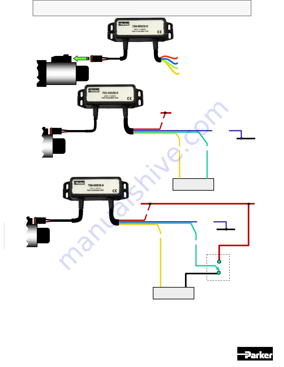
700-00028-0, DFC-4 Fan Driver Unit.

NOTE:-

The ‘Emergency Fan 

MINIMUM SPEED’ configuration 
shown above assumes that the 
controller is being used with an 
inverting operation pressure valve 
and the PWM input is positive logic 
i.e. :

0% PWM = fan full on, 100%PWM = 
fan full off.

Red
Blue

Yellow

Green

+10 to +32V supply I/P
0V Supply I/P

PWM 0V I/P

PWM Signal I/P

Proportional 

valve

0VDC

+10 to +32V max supply input

+ PWM 

output

Engine Control Unit       

( ECU ) 

PWM 0V 

output

1

2

1

2

0VDC

+10 to +32V max supply input

+ PWM 

output

PWM 0V 

output

Emergency Fan 

MINIMUM 
SPEED

relay 

configuration.

NC

NO

1

2

Closing the relay will force the input to 24V supply voltage and the fan will be controlled to 
fully OFF ( the fan may still rotate even in this state, if absolute zero fan speed is required, an 
additional external valve will be needed 
) and will remain in this state until the relay is released.

If the Inverted mode is selected, the relay should be connected to 0V to achieve fan MINIMUM 
SPEED when relay energized.

Connection Guide: -

Proportional 

valve

Proportional 

valve

RED

GREEN

YELLOW

BLUE

Engine Control Unit       

( ECU ) 

RED

BLUE

YELLOW

GREEN

External relay     

( supplied by others )

Summary of Contents for 700-00028-0

Page 1: ...1 Fan Controller Unit 700 00028 0 Application and Information Manual DFC 4 12 24V Direct Connect option Publ 700 00028 0 ver6 February 2006...

Page 2: ...and or advice should be sought from your local distributor or from Parker internal sales departments This driver unit has been designed to interface and operate with Wide supply range 10VDC to 32VDC...

Page 3: ...t under full load 8 Allow wires TO or FROM the unit to short circuit to each other or chassis cabinet e t c 8 Attempt to use this unit in areas of intense RF without adequate screening measures 8 Disc...

Page 4: ...y slope angle e t c are already calculated for us This means that adjustment of the controller is simple with only three potentiometers Dither frequency which is needed to ensure correct repeatable an...

Page 5: ...wer supply to the controller is removed Recommended Parker valve is the ERA121C30 3000psi operation other values are available please consult the IHD catalogue Adjustment Guide NON NON INVERSE INVERSE...

Page 6: ...TE For operational safety if the input PWM signal is below approx 5 the output to the valve is OFF 0 20 40 60 80 100 110 Output Current mA 0 20 30 40 50 60 70 80 100 PWM input 10 90 Output Characteris...

Page 7: ...ommand Input Value 10V 30V 5 to 95 PWM typical range 10 Command Input Frequency 20 to 125Hz 11 Available adjustments I Max I Min Dither Frequency adjust 12 Dither Frequency coil output Preset to 200Hz...

Page 8: ...varying the command signal 15 Set command to maximum PWM 16 Isolate the controller from the power Controller 700 00028 0 is now set and ready for operation 17 Attach the lid to the main controller uni...

Page 9: ...nd signal 16 Set command to minimum PWM 17 Isolate the controller from the power Controller 700 00028 0 is now set and ready for operation 18 Attach the lid to the main controller unit carefully ensur...

Page 10: ...V max supply input PWM output PWM 0V output Emergency Fan MINIMUM SPEED relay configuration NC NO 1 2 Closing the relay will force the input to 24V supply voltage and the fan will be controlled to ful...

Page 11: ...ightweight Aluminum alloy Housing Colour Eggshell Black Surface Finish Powder coated Unit size See above size detail drawings Unit Weight Approx 400 grams including Encapsulation material Cable Wire e...

Page 12: ...12 Parker Hannifin Corporation Fan Drive Systems 14249 Industrial Parkway Marysville OH 43040 Customer Service Department Tel 937 644 4435 Fax 937 642 3639 www parker com hydraulics fandrive...

Reviews: