Chapter 2, ACR8010 Motherboard Hardware Set-Up
33
ACR8010 MOTHERBOARD HARDWARE WIRING
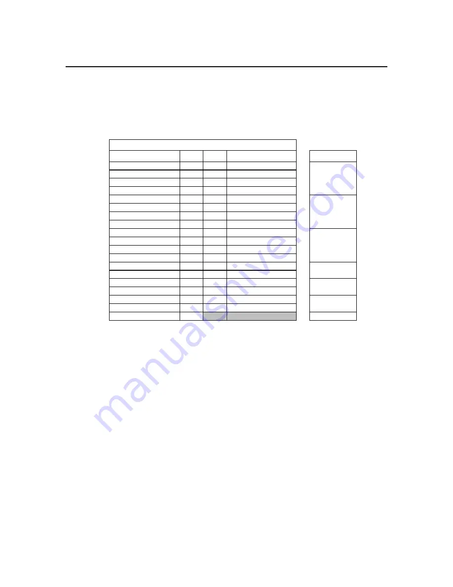
Analog Input/Output (P2)
The analog input/output connections are made through a 37-pin D-style connector on the
side of the ACR8010 motion controller. Refer to Figure 1 for connector location.
Note: P2 is a standard 37-pin female D-plug.
Pin definitions in parentheses are for stepper modules.
P2
Definition Pin
Pin Definition
Module
ASIG-0 ( STEP-0 )
1
20
AGND-0 ( DIR-0 )
ASIG-1 ( STEP-1 )
2
21
AGND-1 ( DIR-1 )
Module 0
ASIG-2 ( STEP-2 )
3
22
AGND-2 ( DIR-2 )
ASIG-3 ( STEP-3 )
4
23
AGND-3 ( DIR-3 )
ASIG-4 ( STEP-4 )
5
24
AGND-4 ( DIR-4 )
ASIG-5 ( STEP-5 )
6
25
AGND-5 ( DIR-5 )
Module 1
ASIG-6 ( STEP-6 )
7
26
AGND-6 ( DIR-6 )
ASIG-7 ( STEP-7 )
8
27
AGND-7 ( DIR-7 )
AIN-0 9
28 AIN-1
AIN-2 10
29 AIN-3
Module
2
AIN-4 11
30 AIN-5
AIN-6 12
31 AIN-7
( LCUR-0 )
13
32
( LCUR-1 )
Module0
( LCUR-2 )
14
33
( LCUR-3 )
( LCUR-4 )
15
34
( LCUR-5 )
Module1
( LCUR-6 )
16
35
( LCUR-7 )
WD-COM 17
36 WD-NO
None
WD-COM 18
37 WD-NC
AGND 19
Module
2
Table 2.13
ACR8010 Analog I/O Connector
Artisan Technology Group - Quality Instrumentation ... Guaranteed | (888) 88-SOURCE | www.artisantg.com


