9
Parker Autoclave Engineers
Instrumentation Products Division
Erie, PA USA
www.autoclave.com | Cat. 02-9221ME
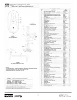
Tube Stop
Thread Die
Chasers
Trip Yoke
Inner Yoke
Figure 10
Positioning tube against tube stop. Die head is shown
in the extreme open position
Collet Assembly
Collar
Spacer Head Assy.
Jam Nut
Figure 11
Setting thread length.
Die head is shown in the closed position
5.5.4 Loosen the jam nut on the spacer head assembly located
under the die head.
5.5.5 While holding one half of the knurled spacer head as-
sembly, turn the other half in the appropriate direction
to lengthen or shorten the spacer head assembly so a
corresponding collar with the same thread size as the
chasers fits snug between the inner collet yoke assembly
and spacer head assembly (Figure 11).
5.5.6 Tighten the jam nut.
Thread Sample Tube
5.6
Turn the machine on. Ensure the chasers are thoroughly
lubricated by the cutting oil.
Note:
Plug or cap the free end of tubing not being coned
or threaded to prevent cuttiing oil from spilling onto the
ground.
5.7
Carefully slide the collet assembly with mounted tube
forward until the cone of the tube touches the chasers.
5.8
Squeeze the bar handles protruding from each side of the
trip yoke and collet assembly toward each other to feed
the tube into the chasers until you see the threads being
cut. Once all four die chasers are cutting, let go of the
handles and the die head will self-feed.
5.9
When the preset length has been threaded, the self-
feeding action of the die head will pull the collet and yoke
assembly against the spacer head which in turn will push
against the trip yoke causing it to automatically open the
die head and release the tubing.
5.10 Turn off the machine and clean the chips out of the die
head assembly to prevent damage when the yoke assem-
bly is pulled away from the die head. Pull collet assembly
with tube mounted in it away from die head.
5.11 Loosen the collet nuts and remove tube. Allow any oil
inside the tubing to drain back into the machine.
Inspect Sample Tube
5.12 Screw a collar onto the tube to check for proper thread
length and depth. The collar should screw on easily and
be able to move slightly side to side. The threads are not
deep enough if the collar won’t screw on easily. If the col-
lar moves up and down lengthwise, then threads are cut
too deep.
Correct length allows 1 to 1-1/2 threads to show above
the collar. See column “L” of Table 3 and Figure 7 for
correct threaded lengths for different tube sizes.
5.13 If the pitch diameter or thread length is not correct,
adjust the machine and thread a new piece of tubing.
Never try to rethread tubing.
Operation After Setting Die Head
5.14 When the die head has been properly adjusted and
sample tubing is produced with proper thread length and
fit, proceed with threading operation of tubing.
5.15 Rotate tube-stop 90° to the left by lifting up, rotating
and letting down (Figure 10). Insert coned, unthreaded
tubing loosely through both collets. Bottom tube end
against tube stop and tighten collet nut on the inner yoke
by hand. Then rotate tube-stop back to original position
and tighten collet nut on inner yoke with spanner wrench.
Pull the inner yoke away from the motor and against the
frame bracket. Tighten the outer collet nut with spanner
wrench.


