background image

02-9242ME

:  AHL Series Pump

Operation & Maintenance Manual  |  04/22

7

Section 6.0

Installation

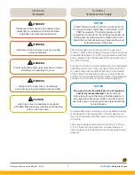
Please read this manual in its entirety before  

attempting to operate an Parker Autoclave  

Engineers high pressure liquid pump

!

WARNING

AHL Pumps have a maximum sound level  

of 90 dBA. Wear hearing protection while working 

with or near the pump.

!

CAUTION

Installation to be performed only by properly 

trained individuals.

!

WARNING

Proper protective safety gear must be worn while 

installing and operating the pump.

!

WARNING

Always bolt the pump to a substantially  

solid surface using the slotted holes provided.

!

WARNING

Section 6.1

Compressed Air Supply

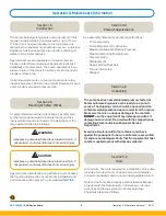
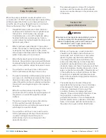
Unless otherwise noted, all air line accessories for 

the pump air drive should have, at minimum, a 1/2

"


FNPT connection. The tubing/piping used to  

connect the components should have the maximum 

ID the pressure rating will allow. Reducing the size 

before the air inlet will reduce air pressure flow and 

reduce flow rate of the pump.

NOTICE

The main air drive connection port on the pump is a 

female 1

"

 FNPT and is located in the spool base housing.  

An additional female 1/8

"

 FNPT air pilot valve connection 

port is located in the middle plate at the opposite side of 

the 1

"

 NPT air inlet.  

This pilot connection must be plumbed to an unregulated 

and filtered air source.  The purpose of this connection 

is to aid in low pressure differential start-up and restart 

of the pump while providing a more accurate pressure 

control.  The pump will not function if this unregulated air 

supply is not connected to the pilot valve supply port.

The use of an air line lubricator is not required 

and is not recommended.

 The oil in the air  

lubricator will cause the factory installed grease to 

be purged from the pump. Once an air lubricator is 

used the pump can never again be operated without 

an air lubricator.

NOTICE

An air line filter with a minimum 5 microns filtration rating 

must be used on the supply line. If the air supply is not 

dry, a mist separator must be used to remove moisture in 

the air line.

The pump is designed to function from 20 psi to 110 psi 

(1.4 to 7.6 bar) air input pressure, however maximum 

inlet air pressure is limited by the maximum liquid output 

pressure.

Summary of Contents for AHL Series

Page 1: ...AHL Series Pump Air Driven High Pressure Liquid Pump Operation and Maintenance Manual Manual 02 9242ME April 2022 ...

Page 2: ...s own analysis and testing is solely responsible for making the final selection of the products and systems and assuring that all performance safety and warning requirements of the application are met The products described herein including without limitation product features specifications designs availability and pricing are subject to change by Parker Hannifin Corporation and its subsidiaries a...

Page 3: ...roduct Specification 6 4 0 Unpacking 6 5 0 Tools 6 6 0 Installation 7 6 1 Compressed Air Supply 7 6 2 Liquid Section 8 7 0 Pump Start Up 8 8 0 Process Media 9 9 0 Pump Functionality 10 10 0 Suggested Maintenance 10 Troubleshooting Information 11 0 Repair Kit Options 11 12 0 AHL Series Drawings 12 13 0 Trouble Shooting Pneumatic Section 15 14 0 Trouble Shooting High Pressure Liquid Section 16 15 0 ...

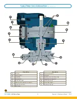
Page 4: ... H L M E N F G O Description Description A Air Inlet I Air Piston Bumper B Top End Cap J Air Piston C Air Muffler K High Pressure Seal Assembly D Air Cylinder L Liquid Inlet Connection E Bottom End Cap M Inlet Check Valve F High Pressure Outlet Connection N Pump Head Body G Outlet Check Valve O Hydraulic Plunger H Pilot Valve ...

Page 5: ...pe 4 PLCS 17 55 445 71 Liquid Inlet Female 1 2 NPT Side View Note Each Mounting Bracket includes 2 9 16 14 29 holes for 1 2 Bolts All dimensions are for reference only and are subject to change without notice Primary Dimensions Inches Secondary Dimensions Millimeters A 1 8 NPT Thread Spool Air Inlet Opposite Main Air Supply 1 4 NPT Thread Isolation Drain Port See Note 8 00 203 20 8 47 215 10 16 94...

Page 6: ... contents carefully examined upon receipt from the carrier Make sure there is no obvious damage to the contents DO NOT use the equipment if any damage is evident If damage has occurred file a claim with the shipper before contacting Parker Autoclave Engineers Service Department Examine all material within the container and check against the packing list to be sure all items are accounted for and a...

Page 7: ...tion port on the pump is a female 1 FNPT and is located in the spool base housing An additional female 1 8 FNPT air pilot valve connection port is located in the middle plate at the opposite side of the 1 NPT air inlet This pilot connection must be plumbed to an unregulated and filtered air source The purpose of this connection is to aid in low pressure differential start up and restart of the pum...

Page 8: ... output flow NOTICE Outlet The outlet tubing ID must at minimum match the same size of the pump check valve gland port Refer to product literature for outlet connections details for each pump Reducing outlet tubing or connection will reduce output liquid flow capacity The high pressure tubing must be rated to at least the maximum pump output pressure WARNING Verify liquid pressure system is protec...

Page 9: ...automatically restart if there is a drop in downstream high pressure DO NOT exceed the maximum liquid pressure and temperature rating specified on the assembly drawing and label for your pump It is recommended to use a liquid relief valve or rupture disk to prevent over pressurization of your high pressure system DO NOT exceed the maximum air drive pressure listed on your pump label WARNING Sectio...

Page 10: ...erse action of step 1 the suction head will change to a compression stroke while the pressurize head will change to a suction stroke 8 The air pistons continue to move until a piston hits the pilot valve assembly in the second end cap which will again cause the spool to shift and divert air to move the pump in the opposite direction Section 4 0 Unpacking Section 10 0 Suggested Maintenance All pump...

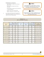
Page 11: ...epair Kit Options Pump Model Number O Ring Material Spool Valve Kit Pilot Valve Kit Air Drive Kit Hydraulic Seal Upper Inlet Check Valve Kit Outlet Check Valve w Seal Full Rebuild Kit AHL33 2DSCTB Buna N RS AHL RP AHL RA AHL 2DC RH AHL33 TB RC 11 B RC 11 B RF AHL33 2DCTB AHL33 2DSCTC FFKM RS AHL RP AHL RA AHL 2DC RH AHL33 TC RC 11 C RC 11 C RF AHL33 2DCTC AHL33 2DSCTV FKM RS AHL RP AHL RA AHL 2DC ...

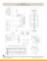
Page 12: ...Operation Maintenance Manual 04 22 02 9242ME AHL Series Pump 12 Section 4 0 Unpacking Section 12 0 AHL33 20 C Series Pump Drawing ...

Page 13: ...02 9242ME AHL Series Pump Operation Maintenance Manual 04 22 13 Section 4 0 Unpacking Section 12 0 AHL66 20SC Series Pump Drawing ...

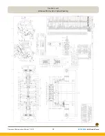
Page 14: ...Operation Maintenance Manual 04 22 02 9242ME AHL Series Pump 14 Section 4 0 Unpacking Section 12 0 AHL118 20SC Series Pump Drawing ...

Page 15: ... d Replace o ring on bottom plunger two piece plunger designs or add Loctite 2760 thread locker with sealant on plunger threads one piece plunger designs Problem Pump will not run and air escapes through the small hole in the spool valve housing Cause Spool valve sleeve o rings are leaking Solution Replace and lubricate spool valve o rings Problem Pump will not run and air escapes through the pilo...

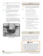
Page 16: ...Solution Assure unregulated pilot air regulated air drive and shutoff valve are arranged as shown in the Air Line Schematic in Section 7 0 Turn off regulated air drive pressure Pressure should now only be supplied to the unregulated pilot connection Press the manual push button switch on either end of Pilot Control Valve see image below This will shift the Pilot Control Valve and then the spool to...

Page 17: ...Maintenance Notes ...

Page 18: ...Operation Maintenance Manual 04 22 02 9242ME AHL Series Pump 18 Maintenance Notes ...

Page 19: ... Generators Compressed Air Gas Filters Condition Monitoring Engine Air Fuel Oil Filtration Systems Hydraulic Lubrication Cool ant Filters Process Chemical Water Microfiltration Filters Nitrogen Hydrogen Zero Air Generators FLUID and GAS HANDLING Aerospace Agriculture Bulk Chemical Handling Construction Machinery Food Beverage Fuel Gas Delivery Industrial Machinery Mobile Oil Gas Transportation Wel...

Page 20: ...0 67 280 900 parker belgium parker com BG Bulgaria Sofia Tel 359 2 980 1344 parker bulgaria parker com BY Belarus Minsk Tel 48 0 22 573 24 00 parker belarus parker com CH Switzerland Etoy Tel 41 0 21 821 87 00 parker switzerland parker com CZ Czech Republic Klecany Tel 420 284 083 111 parker czechrepublic parker com DE Germany Kaarst Tel 49 0 2131 4016 0 parker germany parker com DK Denmark Baller...

Reviews: