Operation & Maintenance Manual | 04/22
02-9242ME
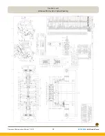
: AHL Series Pump
10
Section 4.0
Unpacking
Section 9.0
Pump Functionality
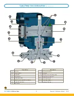
When the pump is installed, maximum system air is
connected to 1/8
"
FNPT pilot air inlet and is sealed off by
pilot valve assembly in the top end cap and does not
enter the spool housing. Regulated air is connected to
the spool housing at the 1
"
FNPT pump inlet.
1.
Regulated inlet air pressure enters the spool
housing and is diverted to the air cylinders and
their pistons, which causes one plunger
to build pressure in one of the hydraulic pump
heads while the second plunger performs a
suction stroke that will pull liquid into the second
hydraulic pump head.
2.
When a hydraulic pump head is in the suction
stroke, the plunger is moving away from the head
causing the inlet check valve to open, which
allows liquid to be drawn into the head while the
outlet check valve is forced closed.
3.
When the hydraulic pump head is building
pressure, the plunger is moving toward the head
compressing the fluid and forcing the inlet check
valve to close and the outlet check valve to open.
4.
The air pistons continue to move until a piston
hits the pilot valve assembly in the end cap.
5.
The pilot control valve shifts allowing max system
air pressure to shift the spool valve so that it now
directs air drive pressure through to the opposite
side of the pistons in the air cylinders and pushes
the air piston and liquid plunger in the opposite
direction.
6.
While the air drive pressure is acting on the
pressure side of the piston, the opposing area of
the piston’s are vented through the exhaust
mufflers.
7.
This action causes the reverse action of step
#1 (the suction head will change to a
compression stroke, while the pressurize head
will change to a suction stroke).
8.
The air pistons continue to move until a piston
hits the pilot valve assembly in the second end
cap which will again cause the spool to
shift and divert air to move the pump in the
opposite direction.
Section 4.0
Unpacking
Section 10.0
Suggested Maintenance
All pumps must be inspected periodically in order to
assure proper and safe operating condition.
Failure to inspect pump can result in serious and
catastrophic harm to personnel and the
surrounding facility.
!
WARNING
A.
Before each pump use, a quick inspection
should be performed to insure there are no
loose bolts, nuts, set screws or check valve
glands. Tighten any lose bolts and fittings
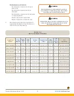
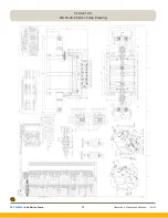
according to the torque values listed on the
pump assembly drawing. A visual inspection
should also be made before each use and at
startup to make sure there is no evidence of fluid
leaks from isolation chamber drain ports, check
valves connections and muffler. If liquid mists out
of the muffler for more than 5 strokes, it is time
to replace your hydraulic high pressure seals.
Refer to the troubleshooting guide for solutions
to these fluid leaks.
B.
The maintenance schedule of the pump
depends on the frequency of use, cleanliness
of media, type of media, cycle rates, output
pressures, cleanliness of air or any other
conditions that may be damaging to seal
integrity. Once a clear pattern develops of how
long a pump is in service before pump
performance declines, it is recommended to
perform maintenance in advance of this time
frame. At minimum, perform maintenance on
the pump once a year as described below.
9.
This alternating action of steps #1 to step #8
continues until the maximum outlet hydraulic
pressure is reached based on the pressure ratio
of the pump.


