HY10-1632-M2.1/US
Parker Hannifin Corporation
Accumulator & Cooler Division
United States
Installation & Disassembly
Bladder Accumulators
8
Assembly & Disassembly
Disassembly of Conventional
Top-Repairable Accumulators
The conventional top-repairable accumulator uses a
gas-end adapter (Item 23) which is retained in the shell
with an anti-extrusion ring (Item 12) exactly like those
used in port assemblies. (See
Figure 10
)
1
Make sure the gas is relieved from the accumulator.
(See Removal of Accumulator from System.)
2
Remove hex jam nut (Item 5) from bladder gas valve
stem (Item 2) using a 1-5/16" socket wrench.
3
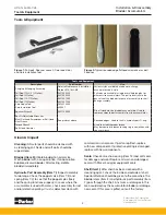
Using a spanner wrench, 085110 0000, remove outer
lock ring (Item 8) on the gas end adapter (Item 23).
4
Push the gas end adapter (Item 23) complete with
the bladder (Item 2) into the shell (Item 1).
5
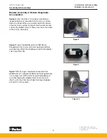
Insert hand into accumulator, remove the o-ring
back-up (Item 16), o-ring (Item 14), and metal
back-up (Item 18). Separate the anti-extrusion ring
(Item 12) from the gas end adapter (Item 23).
6
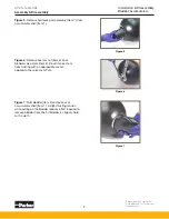
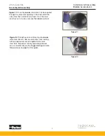
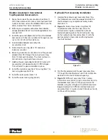
Fold the anti-extrusion ring (Item 12) and remove
from shell (Item 1). (See
Figure 4
).
7
Remove gas end adapter (Item 23) from shell.
8
Remove bladder (Item 2) from shell.
NOTE: Conventional top repairable accumulators
may be repaired by removing the bladder from either
the hydraulic end or the gas end of the accumulator.
Clean & Inspect
Cleaning:
All metal parts should be cleaned with
a cleaning agent. Seals and soft parts should be
wiped clean.
Bladder (Item 2):
Inflate bladder to normal size.
Wash bladder with a soap solution. If soap solution
bubbles, discard bladder. After testing, deflate
bladder immediately.
Hydraulic Port Assembly (Item 7):
Inspect assembly
for damage. Check the poppet valve (Item 7.2) and
spring (Item 7.4) to see that the poppet spins freely
and the spring functions properly. In cases where the
accumulator is used with water, check assembly for rust
and/or defective plating. If rust is detected, clean with
commercial rust remover. If parts are pitted, replace
with new components. If protective plating is damaged,
replace with new components.
Seals:
Check anti-extrusion ring (Item 12) and soft seals
for damage and wear. Replace all worn and damaged
seals with Parker’s original equipment seals.
Shell (Item 1):
After shell has been cleaned with a
cleansing agent, check the inside and outside of shell.
Special attention should be given to the area where
the gas valve and hydraulic assembly pass through the
shell. Any nicks or damages in this area could destroy
the accumulator bladder or damage new seals. If this
area is pitted consult factory.
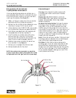
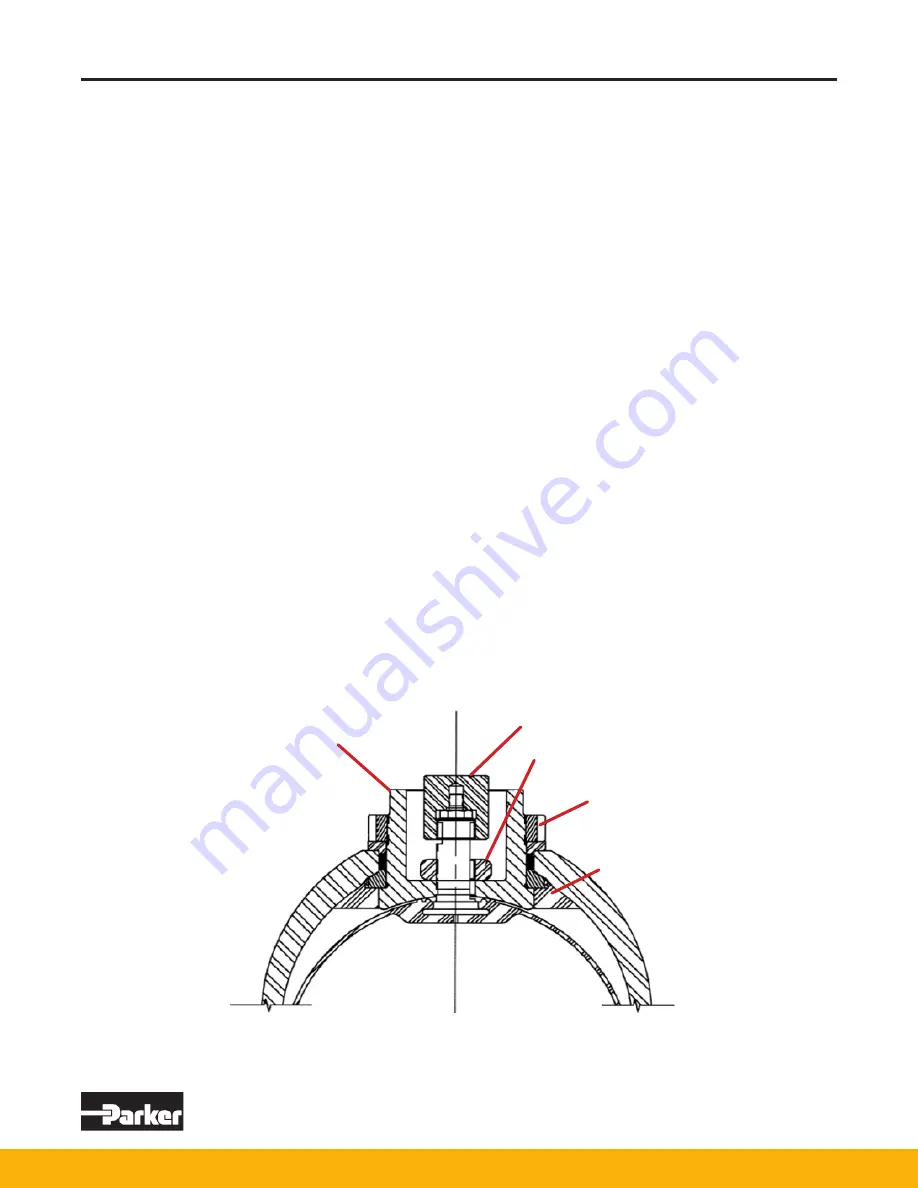
Figure 13
Gas End Adapter
Protective Cap
1-5/16" Hex Nut
Outer Locknut
Anti-Extrusion Ring


