Bulletin HY14-1450-M1/US
Bul 1450-M1pgs.p65, dd
Flow Control Servovalves
8
Parker Hannifin Corporation
Hydraulic Valve Division
Elyria, Ohio, USA
Contamination Resistant
Electrohydraulic Servovalves
The Parker BD series servovalves are ruggedly
designed for use in the industrial market place. From
its inception, the first stage amplifier (pilot valve) has
established a solid history of trouble-free operation in
very harsh environments. Minimum orifice diameters
up to 20 times larger than other servovalve models
substantially increase reliability by reducing problems
due to contamination. The second stage is a closed
center, four-way spool and sleeve assembly which
features rectangular slots in the sleeve. The spool
metering edges exactly match the flow slot edges in
the sleeve to provide linear flow with respect to electri-
cal input. The valves have rated flows up to 40 GPM.
Operation
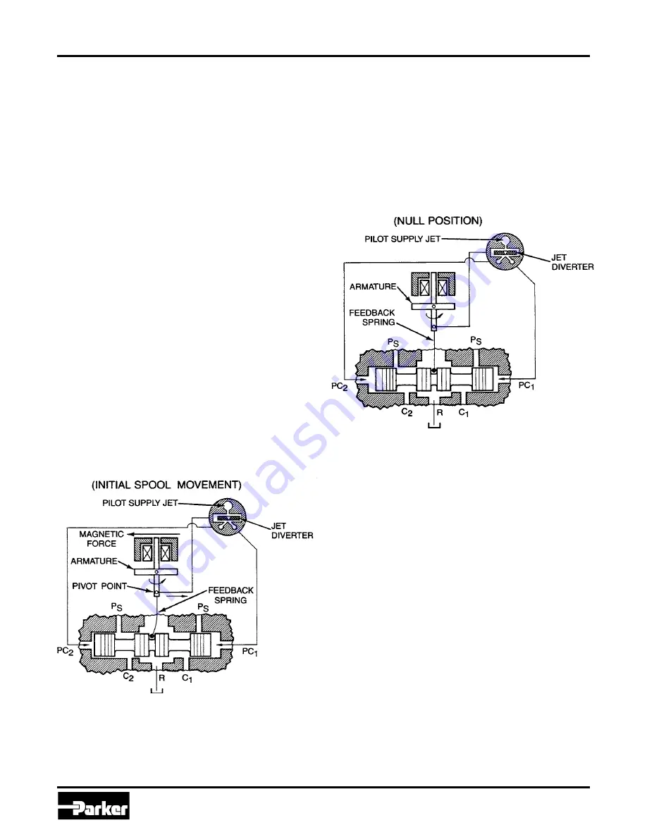
The BD series servovalves operate on a force feed-
back principle between the second stage spool meter-
ing valve and the first stage pilot valve torque motor.
The pilot valve is a single jet pressure recovery unit
that directs a continuing stream of control fluid into a
receiver. The receiver has two outlets that are ported
to the ends of the valve main spool, PC1, and PC2.
The pressure in these ports is equal when the fluid jet
is centered in the receiver opening.
The feedback spring attached to the armature mea-
sures spool position as a force. This force and the
force of the torque motor armature provide the error
displacement of the armature and its diverter blade
window. The window edges divert the jet stream to the
proper receiver outlet to position the spool to the
electrically commanded position.
Figure 2. Servovalve Operation - Command for Flow from Control
Port C2
An electrical signal applied to the pilot valve coil
generates a magnetic force on the armature/diverter
blade assembly, pivoting the assembly and allowing
fluid to flow into PC1. See Figure 2. This positions the
main power spool to the left until the force from the
feedback spring matches the magnetic force. At this
time the diverter blade is re-centered over the receiv-
ing orifices, and the spool motion stops at this position.
Flow, proportional to the input electrical current, is then
metered out the C2 port. Removal of the electrical
signal to the coil unbalances the forces, which re-
verses the armature deflection and drives the spool to
the zero current or null position, as shown in Figure 3.
Changing the polarity of the current to the coil causes
a magnetic force in the opposite direction that results
in flow from the C1 port.
Figure 3. Servovalve Operation - Null Position, Valve in Balance
Servovalve Installation
For maximum valve and system component life, the
hydraulic system should be flushed and filtered to an
absolute filtration of 25 µm before installing the
servovalve. A flushing valve should be used in place of
the servovalve while cleaning the system. These
valves are available from Hydraulic Valve Division, as
follows:
BD15 flushing valve - PN 1200127
BD30 flushing valve - PN 1200128
To keep contaminants from entering the servovalve
and/or hydraulic system, keep the valve shipping cover
in place until immediately prior to installation. Never
leave the port surfaces uncovered and exposed to
contamination. A permanent non-bypass filter should
be installed in the system to assure that the valve
receives a clean supply of oil.
The valve should be mounted as close as possible to
the actuator or motor. It can be mounted in any plane,
but it is best to have the spool as nearly horizontal as
possible.
The servovalve should be set up for the system
operating pressure according to the instructions in the
Operating Pressure
portion of the
Servovalve
Maintenance
section.
Installation Information
Series BD15 and BD30


