background image

Visit our homepage 
for additional support

parker.com/pmde

Bulletin MSG30-8227-INST/UK/DE

Installation Information 

Bypass Valves BPV  
for F1 and T1 pumps

Effective: March 10, 2023

Supersedes: January 13, 2023

Summary of Contents for BPV-F1

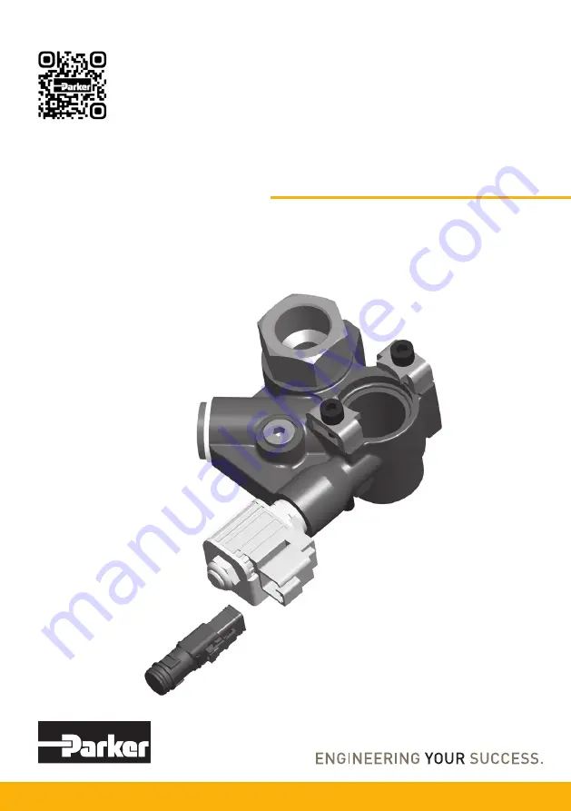
Page 1: ...Visit our homepage for additional support parker com pmde Bulletin MSG30 8227 INST UK DE Installation Information Bypass Valves BPV for F1 and T1 pumps Effective March 10 2023 Supersedes January 13 2023 ...

Page 2: ...ed Leckölleitung muss installiert sein Install the drain line connector which is in cluded with the bypass valve Youneedtousethisconnectorotherwisethe bypassvalve will not work InstallierenSiedenLeckölanschluss derzum Bypassventil gehört Dieser Leckölanschluss und damit eine Leckölleitung muss installiert werden damit das Bypassventil arbeitet DE UK No electric signal Kein elektrisches Sigal Note ...

Page 3: ...ypass valves 24 VDC solenoid is standard on F1 25 41 51 61 F1 81 101 and T1 81 121 12 VDC solenoid is optional on F1 25 41 51 61 F1 81 101 and T1 81 121 Tighten to 8 1 Nm O rings O rings Tighten to 125 15 Nm Deutscher Text auf der Seite 7 UK Suction fitting kit not included IMPORTANT A drain line not included must be installed refer to information on page 2 Drain line connector F1 25 41 51 61 81 1...

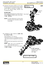
Page 4: ...ssure port on the end cap on top of the pump as shown in the figure to the right and the two figures below The Pressure connector shall be tighten to 50 10 Nm for BPV F1 25 to 61 and T1 81 100 10 Nm for BPV F1 81 to 101 and T1 121 Note As the BPV is symmetrical it can be turned 180 to prevent interference with chassis components it can be utilised for either left hand or right hand pumps Pump pres...

Page 5: ...e diesel engine Remove the protection cup 1 Use 13 mm Wrench 4 and loosen the lock nut 3 Use 4 mm Allen key 5 and screw down the screw 2 until it stops The manual override is now activated NOTE Do not remove the screw 2 If you do that oil will be coming out from the hole Tighten the lock nut 3 5 3 1 2 4 Remember When you have used the manual override function please repair the failure and adjust t...

Page 6: ...tening the cap screws to 20 25 Nm NOTE A suction fitting kit is not included with the pump it must be ordered separately Suction fitting Clamps Cap screws 5 4 3 2 1 F1 25 restrictor included in drain line connector kit 378 1640 Tighten to 125 15 Nm Tighten to 20 to 25 Nm UK 6 Installation of flow restrictor valid only for pump F1 25 Remove items 1 2 3 and 4 Install items 5 and 4 carefully push dow...

Page 7: ... siehe Seite 2 für Installation BPV F1 und T1 Bypass Ventile 24 VDC Magnet ist standard für F1 25 41 51 61 F1 81 101 und T1 81 121 Anzugmoment 8 1 Nm O Ring O Ringe Anzugsmoment 125 15 Nm Sauganschluss nicht enthalten WICHTIG Die Leckölleitung ist nicht ent halten muss installiert werden siehe Information auf Seite 2 Lecköl Anschluss Kit F1 25 41 51 61 81 101 T1 81 121 P N 378 3039 mit Bypass Vent...

Page 8: ...mpe instal lieren Anzugsmoment für Hohlschraube 50 10 Nm für BPV F1 25 bis 61 und T1 81 100 10 Nm für BPV F1 81 bis 101 und T1 121 Anmerkung Da das BPV symmetrisch ist kann es um 180 gedreht werden um eine Störung der Chassis Komponenten zu ver hindern Es kann für die links bzw rechts drehende Pumpe verwendet werden Druckanschluss der Pumpe Sauganschluss der Pumpe Druckan schluss Ventil gehäuse O ...

Page 9: ...hrauben schlüssel der Größe 13 mm 4 und lösen Sie die Sicherungsmutter 3 Benutzen Sie einen Innensechs kantschlüssel Größe 4 mm 5 und ziehen Sie die Schraube 2 fest Die manuelle Nothandbetätigung ist aktiviert Hinweis Nicht die Schraube 2 entfer nen Wenn das passiert kommt Öl aus der Bohrung Die Kontermutter 3 festziehen 5 3 1 2 4 Erinnerung Wenn die manuelle Nothand betätigung nicht mehr benutzt ...

Page 10: ...enthalten Es muß separat bestellt werden 6 Durchflussdrossel Installation Gültig nur für die Pumpe F1 25 Einzelteile Position 1 2 3 und 4 ausbauen Einzelteile 5 und 4 einbauen drücken Sie hierbei sorgfältig Einzelteil 4 gegen den Bo den des Gehäusesitzes Entfernen Sie Einzelteil 4 und drücken Sie jetzt Einzelteil 5 gegen den Boden des Ge häusesitzes ANMERKUNG Bitte sorgfältig arbeiten um den Gehäu...

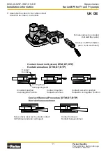
Page 11: ...t Unlocked position unverriegelte Position Contact insertion Kontakt einführen Contact locked in position Kontakt in verriegelter Position Contact Removal Procedure DTM DT DTP Kontakt herausnehmen Screw driver inserted to unlock contact mit Schraubendreher entriegeln Contact removed Kontakt herausnehmen 7 Assemble the cable to the cable contact Anschluß der Kabel siehe Bild Female connector includ...

Page 12: ... locked in place also see page 6 4 Once all contacts are in place insert orange wedge receptacles with half holes align ing with contacts Plugs with con tacts aligning be hind full holes The orange wedge will snap into place NOTE The recep tacle is shown use the same procedure for plug Contact Removal 1 Remove orange wedge using needlenose tongs to pull wedge straight out 2 To remove the contacts ...

Page 13: ...sie he auch Seite 6 4 Sobald alle Kon takte in Position sind setzen Sie den orangefarbe nen Keil ein Anschließend ras tet der Keil ein HINWEIS Die Steckhülse ist fertig Verwenden Sie das gleiche Verfahren für den Stecker Kontakt entfernen 1 Entfernen Sie den orangefar benen Keil mit einer Zange und ziehen ihn gerade heraus 2 Um die Kontakte zu entfernen ziehen Sie vor sichtig den Draht nach hinten...

Page 14: ...fic application as the fact to be a proven component mainly depends on the specific application Christian Jäger General Manger Pump Motor Division Europe Positionsmeldung zur Maschinenrichtlinie 2006 42 EG Produkte der Pump Motor Division Europe PMDE von Parker Hannifin sind nach dem Positionspapier Cetop zur Umsetzung der Maschinenrichtlinie 2006 42 EG in der Fluidtechnik vom Anwendungsbereich de...

Page 15: ...d Offer of Sale WARNING USER RESPONSIBILITY Declaration Verkaufs Angebot Wenden Sie sich bitte wegen eines ausführlichen Verkaufs Angebotes an Ihre Parker Vertretung VERSAGEN ODER UNSACHGEMÄßE AUSWAHL ODER UNSACHGEMÄßE VERWENDUNG DER HIERIN BESCHRIEBENEN PRODUKTE ODER ZUGEHÖRIGER TEILE KÖNNEN TOD VERLETZUNGEN VON PERSONEN ODER SACHSCHÄDEN VERURSACHEN Dieses Dokument und andere Informationen von de...

Page 16: ...V for F1 and T1 pumps MSG30 8227 INST UK DE Installation information Parker Hannifin Manufacturing Sweden AB Pump Motor Division Europe Flygmotorvägen 2 MSG30 8227 INST 461 82 Trollhättan Art No 3781865 10 Sweden Tel 46 0 520 40 45 00 Copyright 2023 www parker com pmde All rights reserved ...

Reviews: