background image

Bulletin HY25-1380-M1/US

Owner’s Manual

Parker Hannifin Corporation

Chelsea Products Division

Olive Branch, MS 38654  USA

2

General Information

10-Bolt Powershift P.T.O.s

Rotating Auxiliary Driveshafts


  WARNING:

  Rotating auxiliary driveshafts are dangerous. You can snag clothes, skin, hair, hands, etc. This can 


cause serious injury or death.

  Do not go under the vehicle when the engine is running.

  Do not work on or near an exposed shaft when the engine is running.

  Shut off the engine before working on the Power Take-Off or driven equipment.

  Exposed rotating driveshafts must be guarded.

Guarding Auxiliary Driveshafts


  WARNING: We strongly recommend that a Power Take-Off and a directly mounted pump be 

used to eliminate the auxiliary driveshaft whenever possible. If an auxiliary driveshaft is used and 

remains exposed after installation, it is the responsibility of the vehicle designer and P.T.O. installer to 

install a guard.

Using Set Screws


  WARNING: Auxiliary driveshafts may be installed with either recessed or protruding set screws. 

If you choose a square head set screw, you should be aware that it will protrude above the hub of 

the yoke and may be a point where clothes, skin, hair, hands, etc. could be snagged. A socket head 

set screw, which may not protrude above the hub of the yoke, does not permit the same amount of 

torquing as does a square head set screw. Also, a square head set screw, if used with a lock wire, will 

prevent loosening of the screw caused by vibration. Regardless of the choice made with respect to a 

set screw, an exposed rotating auxiliary driveshaft must be guarded.

Important: Safety Information and Owner’s Manual

Chelsea Power Take-Offs are packaged with safety information decals, instructions, and an owner’s 

manual. These items are located in the envelope with the P.T.O. mounting gaskets. Also, safety infor-

mation and installation instructions are packaged with some individual parts and kits. 

Be sure to read 

the owner’s manual before installing or operating the P.T.O. Always install the safety information 

decals according to the instructions provided. Place the owner’s manual in the vehicle glove compart-

ment.


  WARNING: Operating the P.T.O. with the Vehicle in Motion

Some Power Take-Offs may be operated when the vehicle is in motion. To do so, the P.T.O. must have 

been properly selected to operate at highway speeds and correctly matched to the vehicle transmission 

and the requirements of the driven equipment.

If in doubt about the P.T.O. specifications and capabilities, avoid operating the P.T.O. when the vehicle 

is in motion. Improper application and/or operation can cause serious personal injury or premature 

 failure of the vehicle, the driven equipment, and/or the P.T.O.

Always remember to disengage the P.T.O. when the driven equipment is not in operation. 

Pump Installation Precautions

Use a bracket to support the pump to the transmission if:

  The pump weighs

 40 pounds [18.4 kg] or more.

  The combined length of the P.T.O. and pump is 

18 inches [45.72 cm] or more from the P.T.O. 


centerline to the end of the pump.

This symbol warns of possible personal injury.

Safety Information (Continued)

Summary of Contents for CHELSEA 267 Series

Page 1: ...December 2009 267 Series 269 Series 277 Series 278 Series 859 Series 867 Series Brought to you by Pro Gear Transmission courtesy of Parker Hannifin Chelsea PTO For parts or service contact us Pro Gear...

Page 2: ...d in any other materials provided from Parker or its subsidiaries or authorized distributors To the extent that Parker or its subsidiaries or authorized distributors provide component or system option...

Page 3: ...for Hino Model 338 17 GMT P T O Connector 18 P T O Combo Valve Installation Sketch 277 278 series Old Style Valve 19 P T O Combo Valve Installation Sketch 277 278 series New Style Valve 20 Caterpilla...

Page 4: ...Bulletin HY25 1380 M1 US Owner s Manual Parker Hannifin Corporation Chelsea Products Division Olive Branch MS 38654 USA IV Parker lchelsea...

Page 5: ...auxiliary equipment being powered Damaged components or equipment could malfunction causing serious personal injury to the vehicle operator or to others nearby To avoid personal injury and or equipme...

Page 6: ...Regardless of the choice made with respect to a set screw an exposed rotating auxiliary driveshaft must be guarded Important Safety Information and Owner s Manual Chelsea Power Take Offs are packaged...

Page 7: ...eed 40 pounds 18 14 kg 2 The combined length of the P T O and pump is 18 inches 45 72 cm or more from the P T O centerline to the end of the pump ALSO Remember to pack the female pilot of the P T O pu...

Page 8: ...unsatisfactory perfor mance of the equipment right from the start Before you order new trucks be sure you re getting the right transmission P T O combination It is of vital importance for efficient p...

Page 9: ...5 x 5 pressure sensitive vinyl label part number 379275 on the visor nearest the operator of the vehicle this must be placed near the P T O visor label 3 Place the one 1 red and white with black lett...

Page 10: ...Bulletin HY25 1380 M1 US Owner s Manual Parker Hannifin Corporation Chelsea Products Division Olive Branch MS 38654 USA 6 Installation Instructions 7 10 Bolt Powershift P T O s Parker lchelsea...

Page 11: ...torque This length change commonly called slip movement is caused by movement of the power train due to torque reactions and chassis deflections Joint operating angles are very important in an auxili...

Page 12: ...250 2 250 2 375 2 375 Distance Across Lugs Snap Ring 2 188 2 656 3 469 3 469 Construction Bearing Diameter 938 938 1 062 1 062 Maximum Operating Speed By Tube Size Solid Shaft Size and Length For spee...

Page 13: ...nstall the guide pins until they bottom out Fig 4 Refer to Page 34 for correct location and use NOTE Do not use sealing compounds because they are generally incompatible with automatic transmission fl...

Page 14: ...aling of P T O to transmission only use gasket furnished with the P T O 6 Position the P T O and secure it with the top capscrew Fig 6 Note Refer to page 34 for proper capscrew installation for the 26...

Page 15: ...ttach the high pressure line to the P T O valve Fig 10 11 Use the special fitting to securely attach the high pressure line to the transmission This fitting is included with the P T O Fig 11 See the c...

Page 16: ...rt 329130 1X 329130 5X 329130 5X 329130 5X MD R H Side Right Press Port 329130 4X 329075 1X 329075 1X 329075 1X HD Top Right Left Press Port 329130 6X 329075 2X 329075 2X 329075 2X HD L H Side Left Pr...

Page 17: ...t page 12 379486 90 Fitting Install in Transmission High Pressure Port MD Left or Right Side HD Left Side Only 379257 Splice Connector 379900 Fuse Holder 10 Amp Fuse White Red Wire 379336 Bracket Indi...

Page 18: ...ing Install in Transmission High Pressure Port MD Left or Right Side HD Left Side Only 379257 Splice Connector 379900 Fuse Holder 10 Amp Fuse White Red Wire 379336 Bracket Indicator Light Blue Wire Po...

Page 19: ...upplied w E O C 328923 5X 5 Ft Optional Cable Run Cable through Grommet in Firewall 16 AWG Wire Blue with Butt Connector 16 AWG Wire Green with Butt Connector Slice Grommet insert in Hole in Firewall...

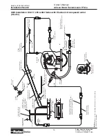
Page 20: ...057 4X Hose A ssembly 328075X Hose Assembly 379252 Butt Connector 379686 1 12 V Solenoid Valve 379686 2 24 V Solenoid Valve 379131 1 Adapter 379449 Adapter 2x 500457 6 Mounting Screw Hose Per Chart Se...

Page 21: ...Grommet in Firewall 379252 Butt Connector 378881 Switch 379306 Spade Terminal 379336 Bracket Positive Terminal of Ignition or Battery 379257 Splice Connector 379900 Fuse Holder Assembly w 10 AMP Fuse...

Page 22: ...d in dash switch simplify the interface for the body builder In order for the customer to utilize the full capability of the P T O transmission Chelsea has design a wiring harness that must be used be...

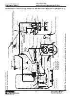
Page 23: ...Ass y w 10 Amp Fuse 379257 Splice Connector Positive Terminal of Ignition or Battery 379664 Red L E D 12 Volt Indicator Light Assembly 379486 90 Fitting Install in Transmission High Pressure Port MD L...

Page 24: ...900 Fuse Holder Ass y w 10 Amp Fuse 379257 Splice Connector Positive Terminal of Ignition or Battery 379664 Red L E D 12 Volt Indicator Light Assembly 379486 90 Fitting Install in Transmission High Pr...

Page 25: ...hey bottom out Fig 3 see page 34 NOTE Do not use sealing compounds because they are generally incompatible with automatic transmission fluid 4 Install the special gasket over the guide pins The ribbed...

Page 26: ...E There are two 2 high pressure ports available Use the port located on the driver s side of the transmission unless there is an interference issue with a pump or driven object Fig 7 7 Using the speci...

Page 27: ...ransmission Continued 9 Complete the assembly by installing the electrical connection Fig 10 NOTE See page 24 26 for electrical connection drawings NOTE If using a rotatable flange see page 34 for bol...

Page 28: ...Fitting Install in Transmission High Pressure Port This Hose Purchased Separately See Hose Chart SK 414 page 27 379336 Bracket 379306 Spade Terminal 378881 Switch 379252 Butt Connector Blue Wire Run W...

Page 29: ...e Electronic Overspeed Controller 329650X 1 0 1 8 4 9 Speed Sensor Extension Cable 328923 10X 10 Ft Supplied w E O C 328923 5X 5 Ft Optional Cable Run Cable through Grommet in Firewall Saddle Splice C...

Page 30: ...379257 Splice Connector 379336 Bracket Positive Terminal of Ignition or Battery 379486 90 Elbow 329057 3X Hose Assembly Purchase Separately 379812 Straight Fitting Install in Transmission High Pressu...

Page 31: ...ssenger Side of Transmission and Under Transmission Output Yoke Trans P T O P T O High Oil P T O P T O Trans Trans P T O Location Pressure Valve Fitting Fitting Valve Hose Location Location Driver LHS...

Page 32: ...C Installation AF Wet Spline 267 Series SK 350 Rev C Install 22 P 84 gasket between P T O and Pump Install 22 P 100 gasket between bearing cap output flange on P T O 379896 500841 1 329057 2X Connect...

Page 33: ...t 329130 5X HD Top Right 329130 8X 329130 1X Hose Assembly 379964 Restrictor 500841 1 90 Elbow Install 35 P 95 Gasket between P T O pump Connect to Transmission Pressure Port See Charts on page 27 for...

Page 34: ...83 Rev B Old Style Pressure Hose Chart Transmission to P T O Trans Location Hose MD Left 329130 1X MD Right 329075 1X HD Left 329130 1X HD Right 329075 2X NWD PAT Output Side Valve Cover Side 28 P 259...

Page 35: ...Spline 277 278 Series SK 383 Rev D New Style Pressure Hose Chart Transmission to P T O Trans Location Hose MD Left 329130 1X MD Right 329075 1X HD Left 329130 1X HD Right 329075 2X NWD PAT Output Sid...

Page 36: ...Transmission to P T O Trans Location Hose MD Left 329130 5X MD Right 329075 1X HD Left 329075 4X HD Top Right 329075 2X Fitting to Transmission Pressure Tap 90 Fitting 379486 Part of 7170 107X Fittin...

Page 37: ...sure Hose Chart Transmission to P T O Trans Location Hose MD Left 329130 5X MD Right 329075 1X HD Left 329075 4X HD Right 329075 2X Fitting to Transmission Pressure Tap 90 Fitting 379486 Part of 7170...

Page 38: ...e capscrews make sure to torque the screws to 16 20 Lbs ft Consideration should be taken on the size and weight of the pump being installed see pages 3 and 4 RA Flange Shown NOTE Reinstalling or tight...

Page 39: ...ther equipment Warning Cold Weather Operation of Powershift P T O s During extreme cold weather operation 32 F 0 C and lower a disengaged Powershift Power Take Off can momentarily transmit high torque...

Page 40: ...Notes Parker Hannifin Corporation Chelsea Products Division Olive Branch MS 38654 USA 36 Parker lchelsea...

Page 41: ...Notes Parker Hannifin Corporation Chelsea Products Division Olive Branch MS 38654 USA 37 Parker lchelsea...

Page 42: ...which result in fretting corrosion on the P T O internal splines as well as the pump external splines Fretting corrosion appears as a rusting and wearing of the pump shaft splines Severe duty applica...

Page 43: ...itions expressly accepted by Seller in writing shall constitute the entire Agreement concerning the items sold and there are no oral or other representations or agreements which pertain there to This...

Page 44: ...Parker Hannifin Corporation Chelsea Products Division 8225 Hacks Cross Road Olive Branch Mississippi 38654 USA Tel 662 895 1011 Fax 662 890 5379 www parker com chelsea FP 03 10 4 5M Parker...

Reviews: